

5.3 IBS CMD configuration software
In the following chapter the configuration package IBS CMD configuration software is presented in short form. This procedure facilitates operation of the WAGO Interbus buscoupler.
Further and specific information is given in the respective operating instructions of the different software packages.
5.3.1 CMD Software Package
Please pay attention that the corresponding interfacing and the function extended should be selected.
The following menu is obtained via the key OK and the password allocated at the program installation.
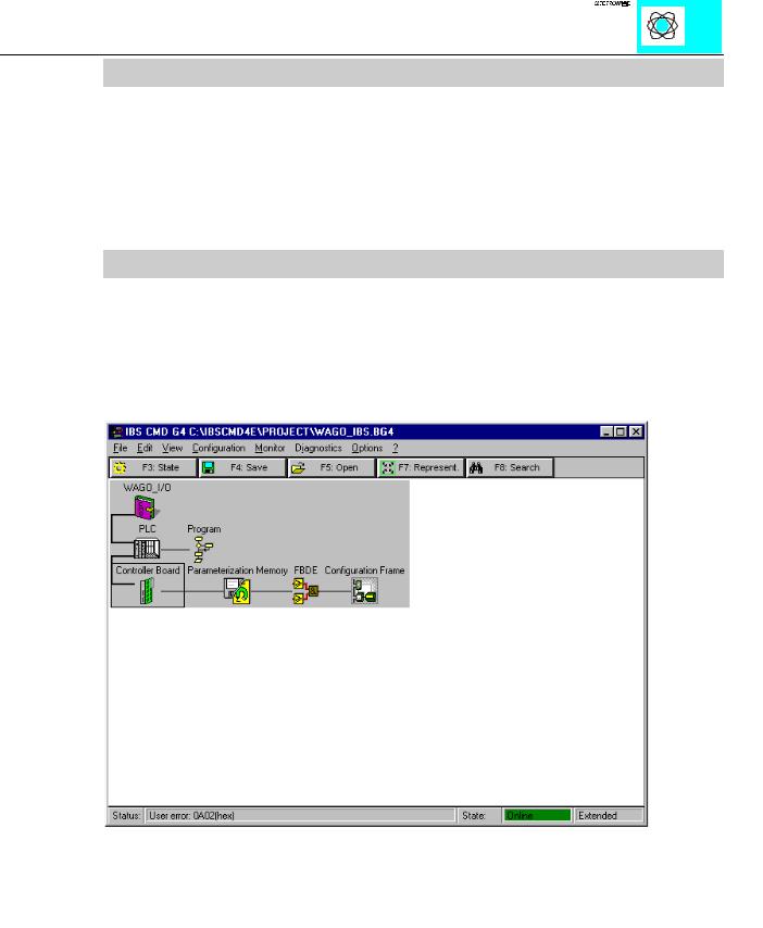
Ill. 10: First menu configuration
This is the first menu for further configuration. From this point the configuration can be made automatically or manually.
INTERBUS S / Configuration |
15 |
:$*2Ç, 2Ç6<67(0

1) Automatic configuration
Ill. 11: Automatic configuration
If the complete fieldbus system with all stations and the master interface is operational, automatic configuration of the connected stations can be called up via the menu „bus structure“. Then the communications are started automatically and the configuration is determined and set.
INTERBUS S / Configuration |
16 |
:$*2Ç, 2Ç6<67(0
2) Ident code
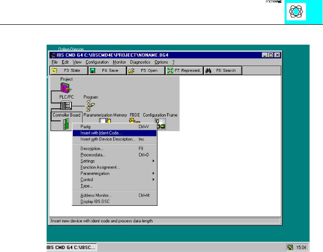
Ill. 12: Insertion of the WAGO I/O System via the Ident code
For manual configuration, the menu item „bus structure“ in the configuration screen must be selected. You will then see Ill. 12.
The corresponding ID code of table 3 and the length of the process data channel must be indicated in the selected submenu. The length is dependent on the module with the largest data length.
INTERBUS S / Configuration |
17 |
:$*2Ç, 2Ç6<67(0

Ill. 13: Insertion of the ID code and the data length
With the finalization of the entries via the key OK, a menu for the definition of the user will appear.
INTERBUS S / Configuration |
18 |
:$*2Ç, 2Ç6<67(0
Ill. 14: Description of user
INTERBUS S / Configuration |
19 |
:$*2Ç, 2Ç6<67(0
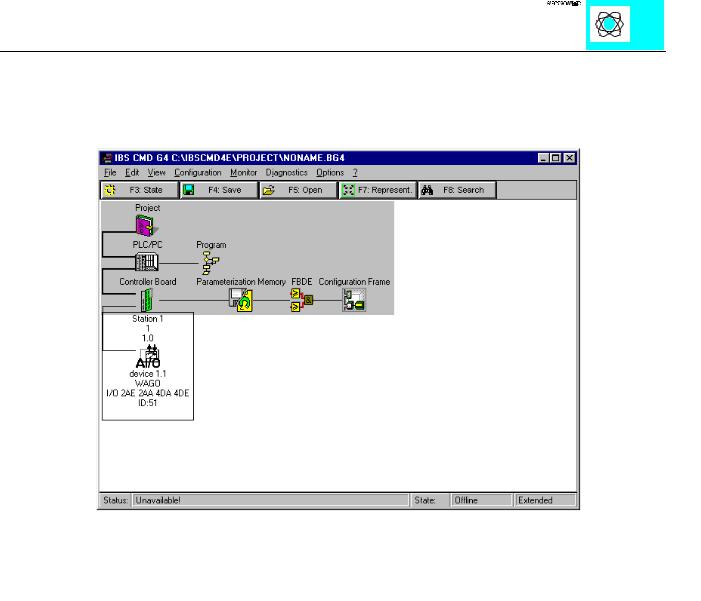
After all data has been entered and stored via OK, the station created with the WAGO Interbus coupler is then integrated into the fieldbus system being set up.
This station is displayed via the bus structure that has now been integrated:
INTERBUS S / Configuration |
20 |
:$*2Ç, 2Ç6<67(0