

2 Buscoupler - INTERBUS S
2.1Buscoupler - Hardware
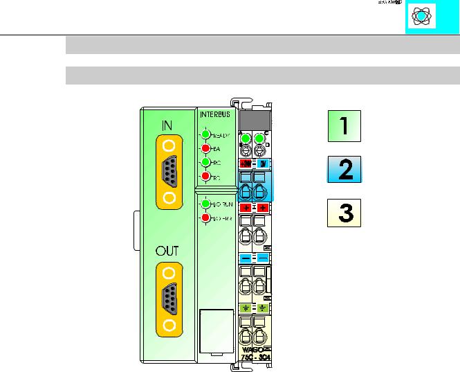
Ill. 2: The INTERBUS buscoupler
The 750-304 Interbus coupler consists of two major electronic sub systems:
left side:
This housing contains the electronics for the coupling to the bus, the processor and the fieldbus connection. (ill. 2.1)
right side:
This housing contains the DC to DC converter and power distribution for the internal K bus, local processor and external 24 V DC connections to other discrete I/O modules. Illustration 2.2 identifies the 24 V DC connection points to supply voltage to I/O modules. Illustration 2.3 identifies the ground connection.
INTERBUS S / Buscoupler |
3 |
:$*2Ç, 2Ç6<67(0
2.2Supply Voltage - Electronics
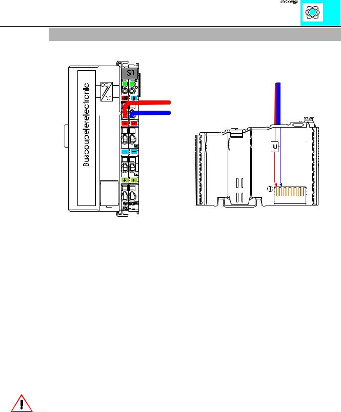
Ill. 3: Termination points for the power supply and the internal electronics
The nominal operating voltage of the Buscoupler and the control electronics in the function modules is 5 V DC. The supply is connected to the first two CAGE CLAMPS at the top of the coupler as seen in Ill. 3.
The 24 V DC supply voltage is generated by an internal voltage regulator (DC/DC converter) and fed to the electronics (5 V DC). The electrical isolation of the external bus system is made by utilizing an optocoupler.
Please note that the power supply for the control electronics in the function modules is made automatically by the data contacts of the following module when it is snapped on the assembly (ill. 3.1). The power supply to the attached I/O modules is provided by gold-plated self-cleaning slide contacts. If an attached module is taken out of the existing configuration, the connection via the K bus is broken and the coupler is able to detect this.
WARNING
If a module is taken out of the existing configuration, there may be undefined states. You should disconnect the power supply when changing anything in the configuration.
INTERBUS S / Buscoupler |
4 |
:$*2Ç, 2Ç6<67(0
2.3Supply Voltage - Field Side
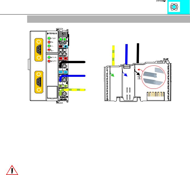
Ill. 4: Termination points for the supply voltage - Field side
The connection of the supply voltage is electrically isolated from the internal electronics. Two CAGE CLAMPS are always connected by a power contact. By this way, the power supply is taken to different points of the configuration.
It is possible to supply the following at the termination points (Ill. 4):
Volts: 24 V DC - Amps: 10 A DC
WARNING!
120 and 230 V AC can only be supplied via modules 750-609, 750-611 and 750-612! The supply modules which are permanently integrated on the buscouplers, can be supplied with 24 V DC only. The current on the power contacts should be max. 10 A.
The voltage is automatically supplied when the function modules are snapped together. Self-cleaning power jumper contacts (P.J.C.s) ensure safe connections (Ill. 4). Female contacts (current supply) are integrated in the buscoupler and I/O housings. The male contacts on the buscoupler and I/O housings supply the voltage to the I/O modules when inserted together from left to right.
The ground (earth) contact makes first and breaks last conforming to electrical standards and can be used as protective grounding.
Depending on the I/O function, some modules do not have P.J.C.s. It is important to note this when assembling a node. Many modules require field side power, many do not. Please review the circuit diagrams of the individual modules. An additional power supply module may be necessary.
INTERBUS S / Buscoupler |
5 |
:$*2Ç, 2Ç6<67(0
When using the supply module 750-601/602, the field supply from the bus coupler is interrupted. From that point a new power supply connection is necessary to provide DC to any additional I/O modules.
WARNING!
The ground ( earth) field side contact should be disconnected when testing the isolation. Otherwise the results could be wrong or even the module could be destroyed.
INTERBUS S / Buscoupler |
6 |
:$*2Ç, 2Ç6<67(0