

8 СЕМЕСТР / АСУ ЭТО / Wago-IO-PRO CAA 2.3.8.5 (5.10.2007) / WAGO-IO-PRO 32 / Docs / eng / 750 / eng_manu / 132 / m013207e
.pdfEnd module, Potential multiplication module,
Separation module
PN750-600, 750-614, 750-616, 750-616/030-000
Technical Description
After the fieldbus node is assembled with the correct buscoupler and selected I/O modules, the end module is snapped onto the assembly. It completes the internal data circuit and ensures correct data flow.
The potential multiplication module allows additional + and - voltage connection points (up to 4 additional). This eliminates external terminal blocks.
Technical Data:
Item Number 750-
Voltage
Current on contacts
Operating temperature
Wire connection
Dimensions (mm) WxHxL
600 |
|
614 |
- |
|
24 V - 230 V AC/DC |
- |
|
max. 10 mA |
0 °C ... |
+ 55 °C |
|
CAGE CLAMP; 0,08 to 2,5 mm²
12 x 64 x 100, (from the upper edge of the carrier rail)
End module, Potential multiplication 750-600,614,616 |
1 |
:$*2Ç, 2Ç6<67(0

Separation module
Technical description:
Use of this module allows increased airand creepage distances between different field voltages within a node.
There are two different types of the separation module. With PN 750-616 you get a module without printing. PN 750-616/030-000 looks like the right one in the above picture.
Technical Data:
Item No.
Dimensions (mm) W x H x L
750-616, 750-616/030-000
12 x 64* x 100, (*from the upper edge of the carrier rail)
End module, Potential multiplication 750-600,614,616 |
2 |
:$*2Ç, 2Ç6<67(0

Supply modules
PN750-601, 602, 609, 610, 611, 612, 613, 615
Technical Description
The supply module provides I/O module power through the power jumper contacts. Maximum current supply to all connected modules is 10 A. Maximum current supply to the modules with fuse holder is 6.3 A. Should higher currents be necessary, intermediate supply modules may be added in the assembly.
The modules 750-601, 609, 615, 610 and 611 are additionally equipped with a fuse holder. The change of the fuse is very easy by drawing out the fuse holder and changing the fuse. A blown fuse is indicated by a LED.
The modules 750-610 and 611 send information about the status of the supply module to the fieldbus coupler through two input bits.
Bit1 |
Bit2 |
Description |
0 |
0 |
voltage < 15 V DC |
1 |
0 |
fuse blown |
0 |
1 |
fuse o.k., voltage o.k. |
Using the supply modules you have to look for the allowed voltage. The following table shows the voltage for the supply modules.
The supply module 750-613 supplies the field side and te internal databus system voltage. The internal system voltage can supply 2 A max. If the sum of the internal current consumption exceeds 2 A, an additional supply module must be added.
Supply modules 750-601,602, 609,615,610,611,613 |
1 |
:$*2Ç, 2Ç6<67(0

Technical Data:
Item Number 750-
Voltage
Current via contacts
Operating temperature
Wire connection
Dimensions (mm) W x H x L
602 |
612 |
613 |
24 V DC |
0 - 230 V AC/DC |
24 V DC |
|
|
(-15%/+20%) |
max. 10 A
0 °C ... + 55 °C
CAGE CLAMP; 0,08 to 2,5 mm²
12 x 64 x 100, (from the upper edge of the carrier rail)
internal current 750-613: max. 2 A
Item Number 750-
Voltage
Current via contacts
Fuse
Operating temperature
Wire connection
Dimensions (mm) W x H x L
601 |
609 |
615 |
24 V DC |
230 V AC |
120 V AC |
max. 6.3 A 5 x 20, 6.3 A
0 °C ... + 55 °C
CAGE CLAMP; 0,08 to 2,5 mm²
12 x 64 x 100, (from the upper edge of the carrier rail)
Item Number 750-
Number of inputs
Current consumption
Internal bitwidth
Voltage
Current via contacts
Fuse
Operating temperature
Wire connection
Dimensions (mm) W x H x L
610 |
|
611 |
|
2 |
|
|
5 mA |
|
|
2 |
|
24 V DC |
|
230 V AC |
max. 6.3 A 5 x 20, 6.3 A
0 °C ... + 55 °C
CAGE CLAMP; 0,08 to 2,5 mm²
12 x 64 x 100, (from the upper edge of the carrier rail)
Supply modules 750-601,602, 609,615,610,611,613 |
2 |
:$*2Ç, 2Ç6<67(0

Binary spacer module
PN 750-622
 1XPEHU RI LQSXWV RU RXWSXWV ,QSXWV RU 2XWSXWV


 9
9


:$*2  9
9
ON |
1 2 3 4 5 |
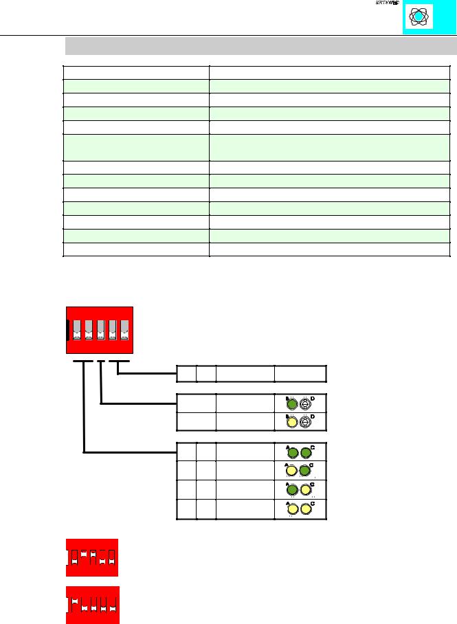
Technical description
The binary spacer module reserves bit-addresses in the WAGO buscoupler.
The number of in or outputs can be chosen by two DIP switches. 2, 4, 6 or 8 bits are possible (1, 2, 3 or 4-channel modules). A third DIP Switch chooses inputs or outputs. The kind of configuration is indicated by means of 3 LEDs even if there is no voltage applied.
The binary spacer module works like a supply module. The power supply must be made for the following modules.
Binary spacer module 750-622 |
1 |
|
:$*2 , 2 6<67(0 |
Technical Data
Item number 750-
Number of inor outputs
Nominal voltage
Internal current consumption
Voltage (field side)
Current via power jumper contacts
Input current (field side)
Isolation
Internal bit width
Configuration
Operating temperature
Wire connection
Dimensions (mm) WxHxL
622
2, 4, 6 or 8
5 V DC internal
10 mA max.
24 V DC (-15%/+20%)
10 A max.
-
500 V system/power supply
2, 4, 6 oder 8
none, optional via software parameter
0°C....+55°C
CAGE CLAMP; 0.08 to 2.5mm2
12 x 64* x 100 (*from upper edge of the carrier rail)
The DIP switches and LEDs are used as follows. When the switch is OFF the LED is also OFF (dark green symbol). When the switch is ON the LED lightens (yellow symbol).
ON
1 2 3 4 5
;;
2))
21
2)) 2)) 21 2)) 2)) 21 21 21
'RQ·W FDUH
,QSXWV
2XWSXWV
%LW [ %LW
%LW [ %LW
%LW [ %LW
%LW [ %LW
Examples:
|
|
ON |
|
|||||||||||||||||
|
|
|
|
|
|
|
|
|
|
|
|
|
|
|
|
|
|
|
|
|
1 |
2 |
3 |
4 |
5 |
6 binary outputs (3x 2-channel output modules) |
|||||||||||||||
|
|
|
|
|
|
|
|
|
||||||||||||
|
|
|
|
|
|
|
|
|
|
|
|
|
|
|
|
|
|
|
||
|
|
|
|
|
|
|
|
|
|
|
|
|
|
|||||||
|
|
|
ON |
|
||||||||||||||||
|
|
|
|
|
|
|
|
|
|
|
|
|
||||||||
|
1 |
2 |
3 |
4 |
5 |
4 binary inputs (2x 2-channel input modules) |
||||||||||||||
|
|
|
|
|
|
|
|
|
|
|
|
|||||||||
Binary spacer module 750-622 |
2 |
|
:$*2 , 2 6<67(0 |