
- •Important Comments
- •Legal Principles
- •Copyright
- •Personnel Qualification
- •Intended Use
- •Symbols
- •Font Conventions
- •Number Notation
- •Scope
- •Abbreviations
- •Scope of Delivery
- •System Configuration
- •Installation
- •Uninstall
- •Start
- •Important Informations
- •WAGO-I/O-PRO 32 V2.2 Overview
- •What is WAGO-I/O-PRO 32
- •Overview of WAGO-I/O-PRO 32 Functions
- •How is a project structured?
- •How do I set up my project?
- •How can I test my project?
- •Debugging
- •Additional Online Functions
- •Additional WAGO-I/O-PRO 32 Features
- •Summary
- •Project Components
- •Project
- •POU (Program Organization Unit)
- •Function
- •Function Block
- •Function Block Instances
- •Calling a function block
- •Program
- •Action
- •Resources
- •Libraries
- •Data types
- •Visualization
- •Languages
- •Instruction List (IL)
- •Modifiers and operators in IL
- •Structured Text (ST)
- •Expressions
- •Valuation of expressions
- •Assignment operator
- •Calling function blocks in ST
- •RETURN instruction
- •IF instruction
- •CASE instruction
- •FOR loop
- •WHILE loop
- •REPEAT loop
- •EXIT instruction
- •Sequential Function Chart (SFC)
- •Step
- •Action
- •Entry or exit action
- •Active step
- •IEC step
- •Qualifier
- •Implicit variables in SFC
- •SFC Flags
- •Alternative branch
- •Parallel branch
- •Jump
- •Function Block Diagram (FBD)
- •The Continuous Function Chart Editor (CFC)
- •Ladder Diagram (LD)
- •Contact
- •Coil
- •Function blocks in the Ladder Diagram
- •Set/Reset coils
- •Debugging, Online Functions
- •Sampling Trace
- •Debugging
- •Breakpoint
- •Single step
- •Single Cycle
- •Change values online
- •Monitoring
- •Simulation
- •The Standard
- •Programming Example
- •Controlling a Traffic Signal Unit
- •Create POU
- •What does TRAFFICSIGNAL do?
- •What does WAIT do?
- •What does SEQUENCE do?
- •What does PLC_PRG do?
- •"TRAFFICSIGNAL" declaration
- •"TRAFFICSIGNAL" body
- •Connecting the standard.lib
- •"WAIT" declaration
- •"WAIT" body
- •"SEQUENCE" first expansion level
- •Create a SFC diagram
- •Actions and transition conditions
- •"SEQUENCE" second expansion level
- •The result
- •TRAFFICSIGNAL simulation
- •Visualizing a Traffic Signal Unit
- •Creating a new visualization
- •Insert element in Visualization
- •The other traffic lights
- •The TRAFFICSIGNAL case
- •The second traffic signal
- •The ON switch
- •Font in the visualization
- •Components of WAGO-I/O-PRO 32
- •The Main Window
- •Menu bar
- •Tool bar
- •Object Organizer
- •Screen divider
- •Work space
- •Message window
- •Status bar
- •Context Menu
- •Options
- •'Project' 'Options'
- •Options for Load & Save
- •Options for User information
- •Options for Editor
- •Autodeclaration
- •Autoformat
- •Declarations as tables
- •Print margins
- •Comment
- •Tab-Width
- •Font
- •Mark
- •Bitvalues
- •Options for the Desktop
- •Options for Colors
- •Options for Directories
- •Options for Log
- •Options for Build
- •Passwords
- •'Sourcedownload'
- •Options for 'Symbol Configuration'
- •Options for 'Macros'
- •Managing Projects
- •'File' 'New'
- •'File' 'Open'
- •'File' 'Close'
- •'File' 'Save'
- •'File' 'Save as'
- •'File' 'Save/Mail Archive'
- •'File' 'Print'
- •'File' 'Printer setup'
- •'File' 'Exit'
- •'Project' 'Build'
- •'Project' 'Rebuild all'
- •'Project' 'Clean all'
- •'Project' 'Translate into another language'
- •Create translation file
- •Editing of the translation file
- •Translate Project (into another Language)
- •'Project' 'Document'
- •'Project' 'Export'
- •'Project' 'Import'
- •'Project' 'Merge'
- •'Project' 'Compare'
- •'Extras' 'Next difference'
- •'Extras' 'Previous difference'
- •'Extras' 'Accept change'
- •'Extras' 'Accept changed item'
- •'Extras' 'Accept properties'
- •'Extras' 'Accept access rights'
- •'Project' 'Project info'
- •'Project' 'Global Search'
- •'Project' 'Global replace'
- •'Project' 'Check'
- •Unused Variables
- •Overlapping memory areas
- •Access conflict
- •Multiple writes to output
- •User groups
- •'Project' 'Passwords for user groups'
- •Managing Objects in a Project
- •Object
- •Folder
- •'New Folder'
- •'Expand nodes' 'Collapse nodes'
- •'Project' 'Object Delete'
- •'Project' 'Object Add'
- •'Project' 'Object Rename'
- •'Project' 'Object Convert'
- •'Project' 'Object Copy'
- •'Project' 'Object Open'
- •'Project' 'Object Access rights'
- •'Project' 'Object properties'
- •'Project' 'Add Action'
- •'Project' 'Open Instance'
- •'Project' 'Show Call Tree'
- •'Projekt' 'Show cross reference'
- •General Editing Functions
- •'Edit' 'Undo'
- •'Edit' 'Redo'
- •'Edit' 'Cut'
- •'Edit' 'Copy'
- •'Edit' 'Paste'
- •'Edit' 'Delete"
- •'Edit' 'Find'
- •'Edit' 'Find next'
- •'Edit' 'Replace'
- •'Edit' 'Input Assistant'
- •Unstructured Display
- •Stuctured Display
- •'Edit''Declare Variable'
- •'Edit' 'Next error'"
- •'Edit' 'Previous error'"
- •'Edit' 'Macros'
- •General Online Functions
- •'Online-Change' Functionality
- •'Online' 'Login'
- •If the system reports
- •'Online' 'Logout'
- •'Online' 'Download'
- •'Online' 'Run'
- •'Online' 'Stop'
- •'Online' 'Reset'
- •'Online' 'Reset (cold)'
- •'Online' 'Reset (original)'
- •'Online' 'Toggle Breakpoint'
- •'Online' 'Breakpoint Dialog Box'
- •'Online' 'Step over'
- •'Online' 'Step in'
- •'Online' 'Single Cycle'
- •'Online' 'Write values'
- •'Online' 'Force values'
- •'Online' 'Release force'
- •'Online' 'Write/Force' Dialog'
- •'Online' 'Show Call Stack'
- •'Online' 'Flow Control'"
- •'Online' 'Simulation'
- •'Online' 'Communication Parameters'
- •Principle of a gateway system
- •What the communications parameters dialog on the local PC shows
- •Setting up the desired gateway server and channel
- •Setting up a new channel for the local gateway server
- •Tips for editing the parameters in the communications parameters dialogue
- •Quick check in the event of unsuccessful connection attempt to the gateway
- •'Online' 'Sourcecode download'
- •'Online' 'Create bootproject'
- •'Online' 'Write file to controller'
- •'Online' 'Load file from controller'
- •'Window' 'Log'
- •Menu Log
- •Storing the project log
- •Window set up
- •'Window' 'Tile Horizontal'
- •'Window' 'Tile Vertical'
- •'Window' 'Cascade'
- •'Window' 'Arrange Symbols'
- •'Window' 'Close All'
- •'Window' 'Messages'
- •Help when you need it
- •'Help' 'Contents and Index'
- •Main Help Window
- •Index Window
- •Context Sensitive Help
- •The Editors
- •Print margins
- •Comment
- •Zoom to POU
- •Open instance
- •Declaration Editor
- •Declaration Part
- •Input Variable
- •Output Variable
- •Input and Output Variables
- •Local Variables
- •Remanent variables
- •Constants, Typed Literals
- •External variables
- •Keywords
- •Variables declaration
- •AT Declaration
- •'Insert' 'Declarations keywords'
- •'Insert' 'Type'
- •Syntax Coloring
- •Shortcut Mode
- •Autodeclaration
- •Line Numbers in the Declaration Editor
- •Declarations as tables
- •'Insert' 'New Declaration'
- •Pragma instructiion
- •Declaration Editors in Online Mode
- •The Text Editors
- •'Insert''Operators'in text editors
- •'Insert''Operand'in text editors
- •'Insert''Function' in text editors
- •'Insert''Function Block' in text editors
- •Calling POUs with output parameters in text editors
- •The text editors in Online mode
- •'Extras' 'Monitoring Options'
- •Breakpoint Positions in Text Editor
- •How do you set a breakpoint?
- •Deleting Breakpoints
- •What happens at a breakpoint?
- •Line Number of the Text Editor
- •The Instruction List Editor
- •IL in Online mode
- •The Editor for Structured Text
- •The Graphic Editors
- •Zoom
- •Network
- •Label
- •Network Comments,'Extras' 'Options'
- •'Insert' 'Network (after)' or 'Insert' "Network (before)"
- •The network editors in the online mode
- •The Function Block Diagram Editor
- •Cursor positions in FBD
- •How to set the cursor in FBD
- •'Insert' 'Assign' in FBD
- •'Insert' 'Jump' in FBD
- •'Insert' 'Return' in FBD
- •'Insert' 'Box' in FBD
- •'Insert' 'Input'
- •'Insert' 'Output'
- •'Extras' 'Negate
- •'Extras' 'Set/Reset'
- •Cutting, Copying, Pasting, and Deleting in FBD
- •The Function Block Diagram in the Online Mode
- •The Ladder Editor
- •Cursor Positions in the LD Editors
- •'Insert' 'Contact'in LD
- •'Insert' 'Parallel Contact'
- •'Insert' 'Function Block in LD'
- •'Insert''Coil' in LD
- •POUs with EN Inputs
- •'Insert' 'Box with EN in LD'
- •'Insert' 'Function Block with EN'
- •'Insert' 'Function with EN'
- •'Insert' 'Insert at blocks in LD
- •'Insert' 'Jump' in LD
- •'Insert' 'Return' in LD
- •'Extras' 'Paste after' in LD
- •'Extras' 'Paste below'in LD
- •'Extras' 'Paste above' in LD
- •'Extras' 'Negate' in LD
- •'Extras' 'Set/Reset' in LD
- •The Ladder Diagram in the Online Mode
- •The Sequential Function Chart Editor
- •Marking Blocks in the SFC
- •'Insert' 'Step Transition (before)'
- •'Insert' 'Step Transition (after)'
- •'Insert' 'Alternative Branch (right)'
- •'Insert' 'Alternative Branch (left)'
- •'Insert' "Parallel Branch (right)"
- •'Insert' 'Parallel Branch (left)'
- •'Insert' 'Jump'
- •'Insert' 'Transition-Jump'
- •'Extras' 'Paste Parallel Branch (right)'
- •'Extras' 'Add label to parallel branch'
- •Delete a label
- •'Extras' 'Paste after'
- •'Extras' 'Zoom Action/Transition'
- •'Extras' "Clear Action/Transition"
- •'Extras' 'Step Attributes'
- •'Extras' 'Time Overview'
- •'Extras' 'Options'
- •'Extras' 'Associate Action'
- •Sequential Function Chart in Online Mode
- •The Continuous Function Chart Editor (CFC)
- •Cursor positions in the CFC
- •'Insert' 'Box' in the CFC
- •‚Insert' ‚Input' in CFC
- •'Insert' 'Output'in CFC
- •'Insert' 'Jump'in CFC
- •'Insert' 'Label' in CFC
- •'Insert' 'Return' in CFC
- •'Insert' 'Comment' in CFC
- •'Insert' 'Input of box' in CFC
- •'Extras' 'Negate' in CFC
- •'Extras' 'Set/Reset' in CFC
- •'Extras' 'EN/ENO' in CFC
- •‚Extras' ‚Properties...' in CFC
- •Selecting elementsin CFC
- •Moving elementsin CFC
- •Copying elementsin CFC
- •Creating connections
- •Deleting connections
- •Changing connections
- •'Extras' 'Connection marker'
- •Insert inputs/outputs "on the fly"
- •Order of execution
- •'Extras' 'Order' 'Display'
- •'Extras' 'Order' 'Order topologically'
- •'Extras' 'Order' 'One forwards'
- •'Extras' 'Order' 'One backwards'
- •'Extras' 'Order' 'To the beginning'
- •'Extras' 'Order' 'To the end'
- •'Extras' 'Order' 'Order everything according to data flow''
- •'Extras' 'Create macro''
- •'Extras' 'Jump into Macro'
- •'Extras' 'Expand macro'
- •'Extras' 'Back one macro level', 'Extras' 'Back all macro level'
- •Feedback paths in CFC
- •CFC in Online mode
- •Overview of the Resources
- •Global Variables
- •Editing Global Variables
- •Several Variables Lists
- •Global Variables
- •Create a Global Variable List
- •Editing Global Variable Lists
- •Editing Remanent Global Variables Lists
- •Global Constants
- •Variable Configuration
- •‚Insert' 'All Instance Paths'
- •Document Frame
- •Document Frame
- •'Extras' 'Make Docuframe File'
- •'Extras' 'Link Docu File'
- •PLC Browser
- •PLC Configuration
- •PLC Selection
- •Task Configuration
- •Which task is being processed?
- •Working in the Task Configuration
- •'Insert' 'Insert Task' or 'Insert' 'Append Task'
- •'Insert' 'Insert Program Call' or 'Insert' 'Append Program Call'
- •'Extras' 'Edit Entry'
- •'Extras' 'Set Debug Task'
- •Sampling Trace
- •'Extras' 'Trace Configuration'
- •'Extra' 'Start Trace'
- •'Extra' 'Read Trace'
- •'Extra' 'Auto Read'
- •'Extra' 'Stop Trace'
- •Selection of the Variables to be Displayed
- •Display of the Sampling Trace
- •'Extras' 'Cursor Mode'
- •'Extras' 'Multi Channel'
- •'Extras' 'Show grid'
- •'Extras' 'Y Scaling'
- •'Extras' 'Stretch'
- •'Extras' 'Compress'
- •'Extras' 'Save Trace'
- •'Extras' 'Load Trace'
- •Watch and Receipt Manager
- •Watch and Receipt Manager in the Offline Mode
- •'Insert' 'New Watch List'
- •'Extras' 'Rename Watch List'
- •'Extras' 'Save Watch List'
- •'Extras' 'Load Watch List'
- •Watch and Receipt Manager in the Online Mode
- •'Extra' 'Monitoring Active'
- •'Extras' 'Write Receipt'
- •'Extras' 'Read Receipt'
- •Force values
- •Library Manager
- •Using the Library Manager
- •Standard Library
- •User-defined Libraries
- •'Insert' 'Additional Library'
- •Remove Library
- •Visualization
- •Visualization
- •Create Visualization
- •Visualization Elements, Insert
- •'Insert' 'Rectangle'
- •'Insert' 'Rounded Rectangle'
- •'Insert' 'Ellipse'
- •'Insert' 'Polygon'
- •'Insert' 'Line'
- •'Insert' 'Curve'
- •'Insert' 'Bitmap'
- •'Insert' 'Visualization'
- •'Insert' 'Button'
- •Working with Visualization Elements
- •Selecting Visualization Elements
- •Modifying Visualization Elements
- •Dragging Visualization Elements
- •Copying Visual Elements
- •Changing the Selection and Insert Mode
- •Status Bar in the Visualization
- •Visualization Elements, Configure
- •'Extras' 'Configure'
- •Placeholder
- •'Extras' 'Placeholder list'
- •Shape
- •Text
- •Line width
- •Colors
- •Motion absolute
- •Motion relative
- •Variables
- •Input
- •ToolTip
- •Bitmap
- •Visualization
- •Additional Visualization Element Functions
- •'Extras' 'Send to Front'
- •'Extras' 'Send to Back'
- •'Extras' 'Select Background Bitmap'
- •'Extras' 'Clear Background Bitmap'
- •'Extras' 'Align'
- •'Extras' 'Select All'
- •'Extras' 'Select Mode'
- •'Extras' 'Element list'
- •'Extras' 'Settings'
- •Operation over the keyboard - in online mode
- •'File' 'Print' in online mode
- •Visualizations in libraries
- •DDE Interface
- •DDE Communication with WAGO-I/O-PRO 32
- •Activating the DDE Interface
- •General Approach to Data
- •Which variables can be read?
- •Linking variables using WORD
- •Linking variables using EXCEL
- •Accessing variables with Intouch
- •Keyboard Commands
- •Use of Keyboard
- •Key Combinations
- •Data Types
- •Standard Data types
- •Data types
- •BOOL
- •Integer Data Types
- •REAL
- •STRING
- •Time Data Types
- •Defined Data Types
- •ARRAY
- •Function Checkbounds
- •Pointer
- •Enumeration
- •Structures
- •References
- •Subrange types
- •The IEC Operators
- •Arithmetic Operators
- •INDEXOF
- •SIZEOF
- •Bitstring Operators
- •Bit-Shift Operators
- •Selection Operators
- •LIMIT
- •Comparison Operators
- •Address Operators
- •Content Operator
- •Calling Operator
- •Type Conversion Functions
- •BOOL_TO Conversions
- •TO_BOOL Conversions
- •Conversion between Integral Number Types
- •REAL_TO Conversions
- •TIME_TO/TIME_OF_DAY Conversions
- •STRING_TO Conversions
- •TRUNC
- •Numeric Functions
- •SQRT
- •ASIN
- •ACOS
- •ATAN
- •EXPT
- •Standard Library Elements
- •String functions
- •LEFT
- •RIGHT
- •CONCAT
- •INSERT
- •DELETE
- •REPLACE
- •FIND
- •Bistable Function Blocks
- •SEMA
- •Trigger
- •R_TRIG
- •F_TRIG
- •Counter
- •CTUD
- •Timer
- •The UTIL.LIB Library
- •UTIL.LIB Library
- •BCD conversion
- •Bit/byte functions
- •EXTRACT
- •PACK
- •PUTBIT
- •UNPACK
- •Mathematical help functions
- •DERIVATIVE
- •INTEGRAL
- •STATISTICS_INT
- •STATISTICS_REAL
- •VARIANCE
- •Controllers
- •Signal generators
- •BLINK
- •Function manipulators
- •CHARCURVE
- •RAMP_INT
- •RAMP_REAL
- •Analogue value processing
- •HYSTERESIS
- •LIMITALARM

142• Components of WAGO-I/O-PRO 32
General Online Functions
4.6.22'Online' 'Simulation'
If Simulation Mode is chosen, then a check( ) will appear in front of the menu item.
In the simulation mode, the user program runs on the same PC under Windows. This mode is used to test the project. The communication between the PC and Simulation Mode uses the Windows Message mechanism.
If the program is not in simulation mode, then the program will run on the PLC. The communication between the PC and the PLC typically runs over the serial interface.
The status of this flag is stored with the project.
4.6.23'Online' 'Communication Parameters'
You are offered a special dialog for setting communication parameters when the communication between the local PC and the run-time system is running over a gateway server in your system. (If the OPC or DDE server is used, the same communications parameters must be entered in its configuration).
4.6.24Principle of a gateway system
Let us examine the principle of the gateway system before explaining the operation of the dialog:
A gateway server can be used to allow your local PC to communicate with one or more run-time systems. The setting concerning which run-time systems can be addressed, which is specifically configured for each gateway server, and the connection to the desired gateway server, is made on the local PC. Here it is possible that both the gateway server and the run-time system(s) can run together on the local PC. If we are dealing with a gateway server which is running on another PC we must ensure that it has been started there. If you are selecting a locally installed gateway server, it automatically starts when you log onto the target run-time system. You can recognise this through the appearance of a WAGO-I/O-PRO 32 symbol on the bottom right in the task bar. This symbol lights up as long as you are connected to the run-time system over the gateway. The menu points Info and Finish are obtained by clicking with the right mousekey on the symbol. Finish is used to switch off the gateway.
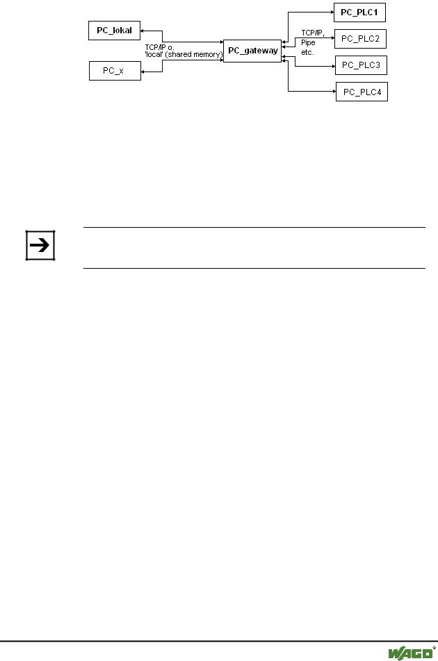
See the following scheme for presenting a gateway system:
WAGO-I/O-SYSTEM 759 WAGO-I/O-PRO 32

Components of WAGO-I/O-PRO 32 |
• 143 |
General Online Functions |
|
|
|
PC_local is your local PC, PC_x is another PC, which gateway addresses. PC_gateway is the PC on which the gateway server is installed, PC_PLC1 through to PC_PLC4 are PCs on which the run-time systems are running. The diagram shows the modules as separated but it is fully possible for the Gateway server and / or run-time systems to be installed together on the local PC.
Note:
Please note that a connection to gateway is only possible over TCP/IP so make sure that your PC is configured appropriately!
The connections from gateway to the various run-time computers can, on the other hand, run over different protocols (TCP/IP, Pipe, etc.).
4.6.25 What the communications parameters dialog on the local PC shows
This dialog is used to select a gateway server for the communicatio with a PLC. Furtheron there can be set up channels for a gateway server which is installed on the local PC so that these channels can be used by other computers which are part of the network.
The current settings can be called up at any time using the button Update.
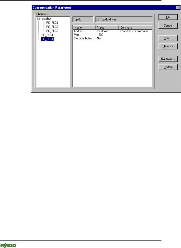
The dialog will appear as follows if the communications parameters have already been configured according to the example in 'Principle of a gatewa system'.:
x Dialog for setting the gateway communications parameters, example
WAGO-I/O-SYSTEM 759 WAGO-I/O-PRO 32

144• Components of WAGO-I/O-PRO 32
General Online Functions
The heading Channels lists two categories of connections:
On the one hand all of the connections are shown which are installed on the currently connected gateway server called 'localhost'. Here the address or the name of this gateway is located on the upper position behind the minus sign, which in our example is running on the local computer. The appropriate address 'localhost' corresponds in the normal case to the IP address 127.0.0.1 of the local computer (PC_local). Below, indented to the right, are three addresses of run-time computers which the gateway channels are set-up to (PC_PLC1 to 3). They could have been configured both from the local PC or from the other PCs (PC_x) which are or were connected to the gateway server.
The second category of the channels describes includes all connections to the gateway which can be set up from your local PC, over this configuration dialog for example. They create the "branch" which leads from the minus sign directly below to PC_PLC1 and PC_PLC4. These channel addresses do not necessarily have to be known yet at the gateway. For PC_PLC4 in the example described above, the configuration parameters are stored locally in the project but they will first be known to the gateway the next time log-in to the run-time system occurs. This has already occurred for PC_PLC1 since the associated gateway address has appeared as an additional "sub-branch" to the "channel tree".
In the central part of the dialog one finds the designation, in each case, of the left selected channel and the associated parameter under Name, Value and
Comment.
4.6.26Setting up the desired gateway server and channel
Setting up the desired gateway server and channel
WAGO-I/O-SYSTEM 759 WAGO-I/O-PRO 32

Components of WAGO-I/O-PRO 32 |
• 145 |
General Online Functions |
|
|
|
To define the connection to the desired gateway server we open the dialog 'Communication Parameters Gateway' by pressing the button Gateway.
x Example dialog, definition of the local connection to the gateway
Here you can enter and/or edit the following:
The type of connection from your computer to the computer on which the gateway server that you want to use is running. If the gateway server is running on the local computer, connection via shared memory ("local") or via TCP/IP is possible; if connection to a different computer is needed, only TCP/IP can be used.
The address of the computer, on which the gateway server that you want to use is running: IP address or the appropriate symbolic name such as e.g. localhost. On initial setup, the standard 'localhost' is offered as the computer name (address), which means that the locally installed gateway would be accessed. The name 'localhost' is set to be identical to the local IP address 127.0.0.1 in most cases, but you may in some cases have to enter this directly into the Address field. If you want to access a gateway server on another computer, you must replace 'localhost' with its name or IP address.
The password for the selected gateway server, if it is on a remote computer. If it is incorrectly entered, or not entered at all, an error message appears.
Note in this connection: you can give the locally installed gateway server a password with the following procedure: click with the right mouse button on the gateway symbol in the lower right portion of the toolbar and select "Change password". A dialog comes up for changing or entering a password. If you access the gateway server locally any password that is entered will not be asked for.
The computer's port on which the gateway server that you wish to use is running, as a rule the correct value for the selected gateway is already given.
If the dialog is closed with OK, the corresponding entry (computer address) appears in the Channels field at the top of the 'Communication parameters' dialog, and below it the channels available on this gateway server.
Setting up the desired channel on the selected gateway server:
Now select one of the channels by clicking on an entry with the mouse. The corresponding parameters will then be shown in the table. If no connection can
WAGO-I/O-SYSTEM 759 WAGO-I/O-PRO 32