- •Documentation for oeMs: CoDeSys sp rte
- •Document Version 2.2
- •1Overview
- •1.1What does "real time extension" mean?
- •1.2The System in Detail
- •2Operation via the Service Icon
- •2.1The System Menu
- •2.1.1Diagnostic
- •2.1.2Startup
- •2.1.3Config
- •2.1.4Access
- •2.1.5Io Drivers
- •3The 3s Standard io Drivers
- •3.1Io driver rtiOdrvHilscherDpm
- •3.1.1The SysLibDpV1.Lib
- •3.2Io driver rtiOdrvFc310x.Sys
- •3.2.1The library SysLibFcdpv1.Sys
- •3.2.2The library fc_SlaveHandling.Lib
- •3.3Io driver rtiOdrvDamp
- •3.4Io driver rtiOdrvApplicom
- •3.6Io Drivers rtiOdrvSja and rtiOwdmPcan
- •3.7Io Drivers rtiOdrvAutomata and rtiOwdmAutomata
- •3.8Io drivers rtiOdrvHms and rtiOwdmHms
- •3.9Io driver rtiOdrvApic
- •3.10Io Driver rtiOwdmCanAutomata
- •3.11Io Driver rtiOwdmSofting
- •4Communication
- •4.1Shared Memory Driver
- •4.2 Tcp/ip Level2 Route Driver
- •5System Diagnosis
- •5.1Bus diagnosis of the io drivers
- •6The Task Configuration together with CoDeSys v2.3
- •6.1Systemereignisse können mit Funktionsaufrufen dem iec-Programm zur Verfügung gestellt werGeneral
- •6.2Task specific watchdog
- •6.3Microseconds as time base
- •6.4Freewheeling task
- •6.5System events
- •6.6DllCall.Lib together with SysLibSystemCall.Lib
- •6.7SysLibCallback.Lib
- •6.8SysLibCom.Lib
- •6.9SysLibFile.Lib
- •6.10SysLibPorts
- •6.11SysLibTime
- •6.12SysLibSockets
- •6.13SysLibShm.Lib
- •6.14SysLibPciCards.Lib
- •7Behaviour in case of runtimeerrors
- •8Appendix
- •8.1The Registry Entries used by the Runtime System
2.1.2Startup
Configure here the startup behaviour of the PLC.
The options:
Start the RTE basic systemservice when booting: The service will be set to "Automatic start" and due to this will be started by the system during boot-up.
RTE basic systemservice startup: Startup behaviour of the system service. Define here whether the service should start the PLC in any case, never, or only if the PLC has been terminated correctly before.
PLC startup: Startup behaviour of the PLC. Define here, whether the PLC should load the boot project in any case, never, or only if the PLC has been terminated correctly before.
Bootproject startup: Startup behaviour of the boot project. Define here, whether the PLC should start the boot project in any case, never, or only if the PLC has been terminated correctly before.

2.1.3Config
Configuration of some basic settings:

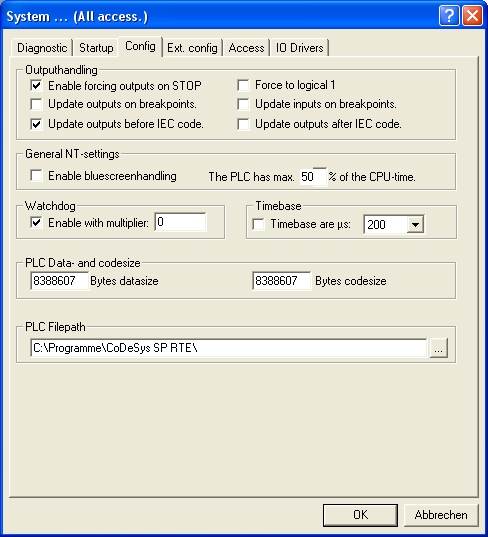
Outputhandling: If option Enable forcing outputs on STOP is activated, then at cycle stop the outputs will be set to 0 once. (Exception: option Force to logical 1 is also activated; then the outputs are set to 1.) .) With the options Update inputs/outputs on breakpoints one can decide if IOs are updated when debugging - including necessary buscycles - even if the update-task is halted on a breakpoint. By default IOs are updated before the IEC-code is executed. With the use of the options Update outputs before/after IEC code this behaviour can be changed. This might be useful, if the task which is defined as update-task, is slow or triggered by event.
General NT-settings: Set here two parameters, which also can affect the operating system: If „Enable bluescreenhandling“ is activated, then the operating system will not be able to show a „bluescreen“ in case of a severe system error (system stop, displaying some error messages), but the system will be "frozen" (for the user), while the SPS keeps running. Of course in this case all functions, which need a running operating system (like file or network access operations), cannot be executed any longer. Set also the percentage of the CPU-time which will max. be available for the PLC.
Watchdog : Here you can activate/deactivate the time control for the tasks and you can assign it with a multiplicator. The multiplicator defines how many multiples of the configured cycle time will be tolerated in case of a time overrun, before the watchdog will produce an error.
Timebase: If needed the time base (default setting 1ms) can be modified. By that a higher resolution can be reached and, for CoDeSys version 2.3 and higher, also cycle times < 1ms are possible. (In the versions lower than 2.3.1 also cycle times < 1ms have been possible, but the times given in the task configuration are now analyzed in µs ! (even if T#1ms is entered in the task configuration))
PLC data- and codesize: Here you can set that size of the code and data memory, which will be allocated by the PLC when starting. The values must match with those configured in the target settings (memory layout).
PLC Filepath: Here the PLC will store files like boot project, retain data etc. The path must exist and must have write access.
Ext. Config
Extended configuration options. These settings are system specific and should not be modified without exact knowledge on the PC hardware !

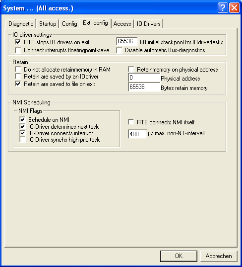
IO driversettings:
At terminating the PLC the IO drivers will only be terminated by the RTE kernel if option RTE Stopps IOdrivers on exit is activated.
If hardware interrupts supporting floating points should be connected, activate option Connect interrupts floatingpoint-save. This option only should be used, if floating point operations are really needed in the interrupt handler, otherwise the resulting loss of performance would be senseless. Inversely an interrupt handler, which executes floating point operations while the option is deactivated, will cause sporadic system crashes.
Activate option Initial stackpool for IO drivers if you want to get the size of the stack for tasks, which are created by IO drivers (not by CoDeSys).
With the option Disable automatic bus diagnostic the system is prevented from writing diagnostic data into the diagnostic address which is used in the PLC configuration of CoDeSys.
Retain:
If both of the options Do not allocate retainmemory in RAM and Retainmemory on physical address are activated, then all variables, which have got the flag “RETAIN” in CoDeSys, will be stored directly in the static RAM. For this purpose the PC hardware must have a SRAM-area on a fixed physical bus address.
Retain are saved by IOdriver normally will not be used and only serves to allow the specific drivers to manage SRAM on their own.
The setting Retain are saved to file on exit does not require a special hardware. But this option presumes that the PLC always will be terminated correctly resp. the PC gets shut down correctly. If this should be guaranteed, especially in industrial environment, using an USP (Uninterruptable Power Supply) is unavoidable.
NMI Scheduling:
If option Schedule on NM is activated, the PLC will not install an interrupt handler for the timer chip of the PC. It will be assumed, that an IO driver is available which can generate or at least can acknowledge cyclic interrupts.
The option RTE connects NMI itself will cause the PLC itself to set an interrupt handler on the NMI vector.
If option IO driver determines next task is activated, the IO driver, which activates and acknowledges the NMI, will determine what the scheduler should do after each interrupt. If it cannot designate this, then the PLC itself will determine, when the operating system and the PLC tasks should be called. For this purpose the PLC will use the value given in max. non-NT-Intervall to check in case of asymmetrical time distribution, which interval should be used for the operating system and which for the PLC task. If possible, this method should not be used, because it assumes asymmetrical interrupt generation and is not flexible.
If an IO driver itself wants to designate an scheduling interrupt, then option IO driver connects interrupt must be activated.
Activate option IO driver synchs high-prio-task if you want to allow an IO driver (that which also defines the scheduler interrupt) to call the top priority task at a certain time which is defined by the driver itself.
