
- •Important Comments
- •Legal Principles
- •Copyright
- •Personnel Qualification
- •Intended Use
- •Symbols
- •Font Conventions
- •Number Notation
- •Scope
- •Important Comments for Starting up
- •Abbreviation
- •The WAGO-I/O-SYSTEM 750
- •Technical Data
- •Manufacturing Number
- •Storage, Assembly and Transport
- •Mechanical Setup
- •Installation Position
- •Total Expansion
- •Assembly onto Carrier Rail
- •Carrier rail properties
- •WAGO DIN Rail
- •Spacing
- •Plugging and Removal of the Components
- •Assembly Sequence
- •Internal Bus / Data Contacts
- •Power Contacts
- •Wire connection
- •Power Supply
- •Isolation
- •System Supply
- •Connection
- •Alignment
- •Field Supply
- •Connection
- •Fusing
- •Supplementary power supply regulations
- •Supply example
- •Power Supply Unit
- •Grounding
- •Grounding the DIN Rail
- •Framework Assembly
- •Insulated Assembly
- •Grounding Function
- •Grounding Protection
- •Shielding (Screening)
- •General
- •Bus Conductors
- •Signal Conductors
- •WAGO Shield (Screen) Connecting System
- •Assembly Guidelines / Standards
- •Fieldbus Controller
- •Fieldbus Controller 750-841
- •Description
- •Hardware
- •View
- •Device Supply
- •Fieldbus Connection
- •Display Elements
- •Configuration and Programming Interface
- •Operating Mode Switch
- •Hardware Address (MAC-ID)
- •Operating System
- •Start-up
- •PLC Cycle
- •Process Image
- •Example of a Process Input Image
- •Example of a Process Output Image
- •Fieldbus specific Process Data Architecture for MODBUS/TCP
- •Digital Input Modules
- •Digital Output Modules
- •Analog Input Modules
- •Analog Output Modules
- •Specialty Modules
- •Data Exchange
- •Memory Areas
- •Addressing
- •Addressing the I/O Modules
- •Address Range
- •Absolute Addresses
- •Data Exchange between MODBUS TCP Master and I/O Modules
- •Data Exchange between Ethernet IP Master and I/O Modules
- •Data Exchange between PLC Functionality (CPU) and I/O Modules
- •Data Exchange between Master and PLC Functionality (CPU)
- •Example MODBUS TCP Master and PLC functionality (CPU)
- •Comparison of MODBUS TCP Addresses and IEC 61131-3 Addresses
- •Starting up an ETHERNET TCP/IP fieldbus node
- •Connecting PC and Fieldbus Node
- •Determining IP Addresses
- •Allocating the IP Address to the Fieldbus Node
- •Testing the Function of the Fieldbus Node
- •Deactivating the BootP Protocol
- •Programming the PFC with WAGO-I/O-PRO CAA
- •WAGO-I/O-PRO CAA library elements for ETHERNET
- •IEC 61131-3-Program transfer
- •Transmission via the Serial Interface
- •Transmission by the Fieldbus
- •Information on the web-based management system
- •LED Display
- •Blink code
- •Fieldbus status
- •Node status
- •Fault Message via Blink Code from the I/O-LED
- •Supply voltage status
- •Fault behavior
- •Fieldbus failure
- •Internal bus fault
- •Technical Data
- •I/O Modules
- •General
- •Digital Input Modules
- •Digital Output Modules
- •Analog Intput Modules
- •Analog Output Modules
- •Counter Modules
- •ETHERNET
- •General
- •Network Architecture – Principles and Regulations
- •Transmission Media
- •Network Topologies
- •Coupler Modules
- •Important Terms
- •Network Communication
- •Protocol layer model
- •Communication Protocols
- •ETHERNET
- •Channel access method
- •IP-Protocol
- •IP Multicast
- •TCP Protocol
- •Application Protocols
- •MODBUS
- •Ethernet/IP
- •BootP (Bootstrap Protocol)
- •HTTP (HyperText Transfer Protocol)
- •DHCP (Dynamic Host Configuration Protocol)
- •DNS (Domain Name Systems)
- •SNTP-Client (Simple Network Time Protocol)
- •FTP-Server (File Transfer Protocol)
- •SNMP V1 (Simple Network Management Protocol)
- •Configuration of SNMP
- •Description of MIB II
- •IpNetToMediaTable
- •Traps
- •SMTP (Simple Mail Transfer Protocol)
- •MODBUS Functions
- •General
- •Use of the MODBUS Functions
- •Description of the MODBUS Functions
- •Function Code FC1 (Read Coils)
- •Function Code FC2 (Read Input Discretes)
- •Function Code FC3 (Read multiple registers)
- •Function code FC4 (Read input registers)
- •Function Code FC5 (Write Coil)
- •Function Code FC6 (Write single register)
- •Function Code FC11 (Get comm event counter)
- •Function Code FC15 (Force Multiple Coils)
- •Function Code FC16 (Write multiple registers)
- •Function Code FC22 (Mask Write Register)
- •Function Code FC23 (Read/Write multiple registers)
- •MODBUS Register Mapping
- •Internal Variables
- •Description of the internal variables
- •Watchdog (Fieldbus failure)
- •Watchdog Register:
- •Diagnostic Functions
- •Configuration Functions
- •Firmware Information
- •Constant Registers
- •Ethernet/IP (Ethernet/Industrial Protocol)
- •General
- •Characteristics of the Ethernet/IP Protocol Software
- •Object model
- •General
- •Classes
- •CIP Common Classes
- •Static Assembly Instances
- •Application examples
- •Test of MODBUS protocol and fieldbus nodes
- •Visualization and control using SCADA software
- •Use in Hazardous Environments
- •Foreword
- •Protective measures
- •Classification meeting CENELEC and IEC
- •Divisions
- •Explosion protection group
- •Unit categories
- •Temperature classes
- •Types of ignition protection
- •Classifications meeting the NEC 500
- •Divisions
- •Explosion protection groups
- •Temperature classes
- •Identification
- •For Europe
- •For America
- •Installation regulations

ETHERNET • 115
Network Architecture – Principles and Regulations
Cabling guidelines
"Structured Cabling" specifies general guidelines for network architecture of a LAN, establishing maximum cable lengths for the grounds area, building and floor cabling.
Standardized in EN 50173, ISO 11801 and TIA 568-A, "Structured Cabling" forms the basis for a future-orientated, application-independent and costeffective network infrastructure.
The cabling standards define a domain covering a geographical area of 3 km and for an office area of up to 1 million square meters with 50 to 50,000 terminals. In addition, they describe recommendations for setting up of a cabling system.
Specifications may vary depending on the selected topology, the transmission media and coupler modules used in industrial environments, as well as the use of components from different manufacturers in a network. Therefore, the specifications given here are only intended as recommendations.
5.2.3 Coupler Modules
There are a number of hardware modules that allow for flexible arrangement for setting up an ETHERNET network. They also offer important functions, some of which are very similar.
The following table defines and compares these modules and is intended to simplify the correct selection and appropriate application of them.
Module |
Characteristics/application |
ISO/OSI |
|
|
layer |
Repeater |
Amplifier for signal regeneration, connection on a physical level. |
1 |
|
|
|
Bridge |
Segmentation of networks to increase the length. |
2 |
|
|
|
Switch |
Multiport bridge, meaning each port has a separate bridge |
2 (3) |
|
function. |
|
|
Logically separates network segments, thereby reducing network |
|
|
traffic. |
|
|
Consistent use makes ETHERNET collision-free. |
|
|
|
|
Hub |
Used to create star topologies, supports various transmission |
2 |
|
media, does not prevent any network collisions. |
|
|
|
|
Router |
Links two or more data networks. |
3 |
|
Matches topology changes and incompatible packet sizes (e.g. |
|
|
used in industrial and office areas). |
|
|
|
|
Gateway |
Links two manufacturer-specific networks which use different |
4-7 |
|
software and hardware (i.e., ETHERNET and Interbus-Loop). |
|
|
|
|
Tab. 5-2: Comparison of Coupler Modules for Networks
WAGO-I/O-SYSTEM 750
ETHERNET TCP/IP

116 • ETHERNET
Network Architecture – Principles and Regulations
5.2.4 Important Terms
Data security
If an internal network (Intranet) is to be connected to the public network (e.g., the Internet) then data security is an extremely important aspect.
Undesired access can be prevented by a Firewall.
Firewalls can be implemented in software or network components. They are interconnected in a similar way to routers as a switching element between Intranets and the public network. Firewalls are able to limit or completely block all access to the other networks, depending on the access direction, the service used and the authenticity of the network user.
Real-time ability
Transmission above the fieldbus system level generally involves relatively large data quantities. The permissible delay times may also be relatively long (0.1...10 seconds).
However, real-time behavior within the fieldbus system level is required for ETHERNET in industry.
In ETHERNET it is possible to meet the real-time requirements by restricting the bus traffic (< 10 %), by using a master-slave principle, or also by implementing a switch instead of a hub.
MODBUS/TCP is a master/slave protocol in which the slaves only respond to commands from the master. When only one master is used, data traffic over the network can be controlled and collisions avoided.
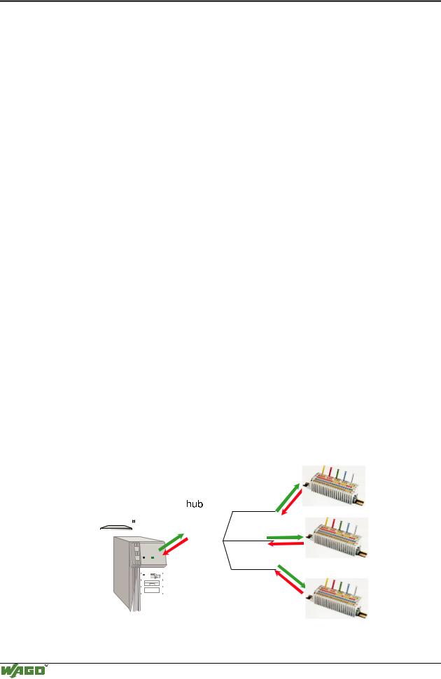
Shared ETHERNET
Several nodes linked via a hub share a common medium. When a message is sent from a station, it is broadcast throughout the entire network and is sent to each connected node. Only the node with the correct target address processes the message. Collisions may occur and messages have to be repeatedly transmitted as a result of the large amount of data traffic. The delay time in a Shared ETHERNET cannot be easily calculated or predicted.
|
|
|
|
|
|
|
|
|
|
|
|
|
|
|
|
|
|
|
|
|
|
|
|
|
|
|
|
|
|
|
|
|
|
|
|
|
|
|
|
|
|
|
|
|
|
|
|
|
|
|
|
|
|
|
|
|
|
|
|
|
|
|
|
|
|
|
|
|
|
|
|
|
|
|
|
|
|
|
|
|
|
|
|
|
|
|
|
|
|
|
|
|
|
|
|
|
|
|
|
|
|
|
|
|
|
|
|
|
|
|
|
|
|
|
|
|
|
|
|
|
|
|
|
|
|
|
|
|
|
|
|
|
|
|
|
|
|
|
|
|
|
|
|
|
|
|
|
|
|
|
|
|
|
|
|
|
|
|
|
|
|
|
|
|
|
|
|
|
|
|
|
|
|
|
|
|
|
|
|
|
|
|
|
|
|
|
|
|
|
|
|
|
|
|
|
|
|
|
|
|
|
|
|
|
|
|
|
|
|
|
|
|
|
|
|
|
|
|
|
|
|
|
|
|
|
|
|
|
|
|
Fig. 5-6: Principle of Shared ETHERNET |
G012910e |
WAGO-I/O-SYSTEM 750
ETHERNET TCP/IP

ETHERNET • 117
Network Architecture – Principles and Regulations
Deterministic ETHERNET
The TCP/IP software or the user program in each subscriber can limit transmittable messages to make it possible to determine real-time requirements. At the same time the maximum medium message rate (datagram per second), the maximum medium duration of a message, and the minimum time interval between the messages (waiting time of the subscriber) is limited.
Therefore, the delay time of a message is predictable.
Switched ETHERNET
In the case of Switched Ethernet, several fieldbus nodes are connected by a switch. When data from a network segment reaches the switch, it saves the data and checks for the segment and the node to which this data is to be sent. The message is then only sent to the node with the correct target address. This reduces the data traffic over the network, extends the bandwidth and prevents collisions. The runtimes can be defined and calculated, making the Switched Ethernet deterministic.
|
|
|
|
|
|
|
|
|
|
|
|
|
|
|
|
|
|
|
|
|
|
|
|
|
|
|
|
|
|
|
|
|
|
|
|
|
|
|
|
|
|
|
|
|
|
|
|
|
|
|
|
|
|
|
|
|
|
|
|
|
|
|
|
|
|
|
|
|
|
|
|
|
|
|
|
|
|
|
|
|
|
|
|
|
|
|
|
|
|
|
|
|
|
|
|
|
|
|
|
|
|
|
|
|
|
|
|
|
|
|
|
|
|
|
|
|
|
|
|
|
|
|
|
|
|
|
|
|
|
|
|
|
|
|
|
|
|
|
|
|
|
|
|
|
|
|
|
|
|
|
|
|
|
|
|
|
|
|
|
|
|
|
|
|
|
|
|
|
|
|
|
|
|
|
|
|
|
|
|
|
|
|
|
|
|
|
|
|
|
|
|
|
|
|
|
|
|
|
|
|
|
|
|
|
|
|
|
|
|
|
|
|
|
|
|
|
|
|
|
Fig. 5-7: Principle of Switched ETHERNET |
G012909e |
WAGO-I/O-SYSTEM 750 ETHERNET TCP/IP