

Fieldbus Controller 750-841 • 85
Programming the PFC with WAGO-I/O-PRO CAA
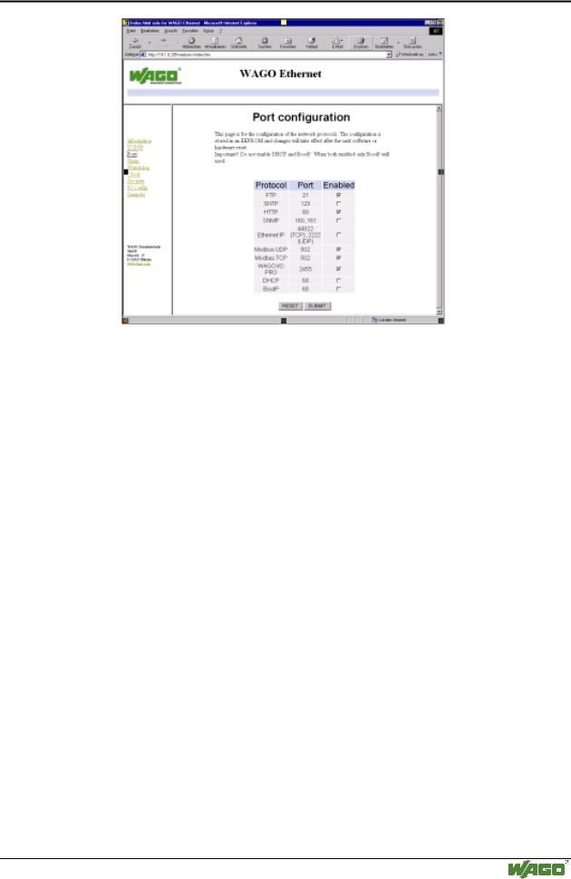
6.A list of all protocols supported by the controller is displayed. The BootP protocol is activated by default. To disable the protocol, click on the check box after BootP to remove the check mark.
7.You can disable other protocols you do not need in a similar way, or enable protocols you wish to use. It is possible to enable several protocols at the same time, since each protocol uses a different port.
8.To store the protocol selection, click the SUBMIT button and then perform a hardware reset. To do this, either switch off the power supply of the controller or press down the operating mode switch.
9.The protocol settings are now stored EEPROM and the controller is ready to operate.
3.1.7Programming the PFC with WAGO-I/O-PRO CAA
The WAGO 750-841 Programmable Fieldbus Controller (PFC) combines the functionality of an ETHERNET fieldbus coupler with the functionality of a Programmable Logic Controller (PLC). When the PFC is used as a PLC, all or some of its I/O modules can be control locally with the use of WAGO-I/O- PRO CAA. WAGO-I/O-PRO CAA is an IEC 61131-3 programming tool that is used to program and configure the 750-841 PFC. I/O modules which are not controlled locally (i.e., not controlled as a PLC), can be controlled remotely through the 10/100 Mbps ETHERNET Fieldbus port.
WAGO-I/O-SYSTEM 750 ETHERNET TCP/IP
86 • Fieldbus Controller 750-841
Programming the PFC with WAGO-I/O-PRO CAA
Note
To perform IEC 61131-3 programming in the 750-841 PFC, the WAGO-I/O- PRO port must be enabled. Enable and Disabling of this port is done with a checkbox in the “Port configuration” web page.
The purpose of this section is not to provide a comprehensive lesson on WAGO-I/O-PRO CAA programming. Instead, it highlights important programming and configuration notes of the IEC 61131-3 program when it is used with the 750-841 PFC.
More information
For a detailed description of how to use the software, please refer to the WAGO-I/O-PRO CAA manual. An electronic copy of this manual can be found on WAGO’s web site: www.wago.com
1.To start the WAGO-I/O-PRO CAA, click the Start menu item
Programs/CoDeSys for Automation Alliance/CoDeSys V2.3/ CoDeSys V2.3 .
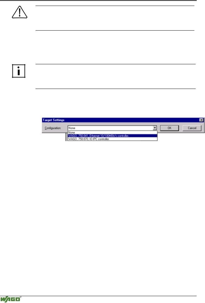
A dialog window will open. Select the target system for programming.
2.Choose WAGO, 750-841, Ethernet 10/100Mbps controller from the pull down list and click the OK button.
3.You can now create a new project in WAGO-I/O-PRO CAA via its menu item File/New. A dialog window will prompt you to select the programming language (i.e., IL, LD, FBD, SFC, etc.).
4.To access I/O modules of your node, the module configuration must first be mapped in the file "EA-config.xml". This file defines which system has write access to each particular I/O module (i.e., the IEC 61131-3 program, MODBUS TCP Fieldbus, or Ethernet IP Fieldbus).
This file can be generated in two different ways:
-in WAGO-I/O-PRO CAA
-in the “EA-config.xml” file stored in the controller.
Configuration with WAGO-I/O-PRO
1.To configure the I/O of the fieldbus node in WAGO-I/O-PRO, select the Resources tab in the left window of the screen, then double click on PLC configuration in the tree structure.
2.The tree structure for the PLC configuration is displayed in the center window. Click on the plus sign (+) in front of Fieldbus Assignment to expand the tree structure, which then displays the text Controller[FIX] for the 750-841 controller.
WAGO-I/O-SYSTEM 750 ETHERNET TCP/IP
Fieldbus Controller 750-841 • 87
Programming the PFC with WAGO-I/O-PRO CAA
3.You can add to the tree structure in accordance with the hardware that you have by right-clicking the mouse button on the text Controller[FIX] and choosing Append Module in the context-sensitive menu that appears.
4.Add a module to the tree structure for each module in your node that supplies or expects data in bits or words.
Note
The number of modules that you add must agree with the physical hardware present (except for supply modules, potential multiplication modules, and end modules).
5.For each module added, click on the text Module[var] and then click on the Module parameters tab in the right-hand dialog window. From the dialog window, select the device (Index 10000) that will control the I/O module in the "Value" column. Your options include:
-PLC (The PFC controls its I/O locally)
-fieldbus 1 (A MODBUS TCP Fieldbus Master controls the I/O module)
-fieldbus 2 (An Ethernet IP Fieldbus Master controls the I/O module)
6.When you have completed the assignments, you can start programming with the IEC 61131-3 program tool. The configuration file “EA-config.xml” is generated as soon as you compile the project.
More information
For a detailed description on how to use the software, please refer to the WAGO-I/O-PRO CAA manual. An electronic copy of this manual can be found on WAGO’s web site: www.wago.com
WAGO-I/O-SYSTEM 750 ETHERNET TCP/IP

88 • Fieldbus Controller 750-841
Programming the PFC with WAGO-I/O-PRO CAA
Configuration with the “EA-config.xml” file
Note
If you wish to directly assign the module mapping using the EA-config.xml file stored in the controller, you must not have previously stored any configuration settings in WAGO-I/O PRO, since this file will be overwritten by the entries in WAGO-I/O-PRO on performing a download
1.Open the FTP client you wish to use (e.g., “LeechFTP”, which is freely downloadable on the Internet).
2.To access the file system of the controller, enter the IP address of the controller in the FTP client. Also, set the user name to admin and the password to wago. The “EA-config.xml” file can be found in the folder etc. on the PFC server.
3.Copy the file into a local directory on your PC and open it with a text editor (e.g., “NotePad”). The following syntax is already prepared in the file:
4.The fourth line contains the necessary information for the first module. The entry [MAP=“PLC“] assigns control rights to the IEC 61131-3 program for the first module. If you want to change the control setting, replace “PLC” with “FB1” for control rights from MODBUS TCP, or with “FB2” for control from Ethernet IP.
5.Now add under the fourth line the same syntax for each individual module with the appropriate control assignment:
<Module ITEM NO.=““ MAP=“(e.g.) PLC” LOC=“ALL”></Module>.
Note
The number of line entries must agree with the number of hardware modules present in your node.
6.Save the file and download it back to the file system of the controller using the FTP client.
7.You can now start programming with WAGO-I/O-PRO CAA.
More information
For a detailed description on how to use the software, please refer to the WAGO-I/O-PRO CAA manual. An electronic copy of this manual can be found on WAGO’s web site: www.wago.com
WAGO-I/O-SYSTEM 750 ETHERNET TCP/IP