

Feldbus-Koppler/-Controller • 77
Fieldbus Controller 750-806
3.2.5.3 Addressing
3.2.5.3.1 Fieldbus Specific
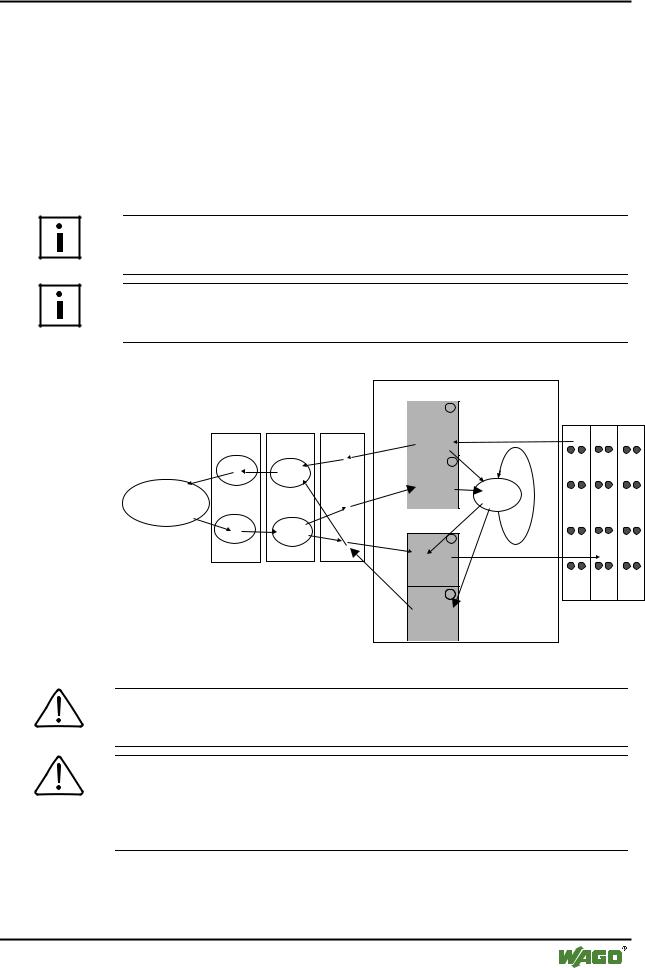
Once the supply voltage is applied, the Assembly Object maps data from the process image. As soon as a connection is established, a DeviceNet Master (scanner) can address and access the data by "Class", "Instance" and "Attribute" or read and/or write the data using I/O connections.
Data mapping depends on the selected Assembly instance of the static assembly or on the application specific determination with the dynamic Assembly.
Further information
The Assembly Instances of the static Assembly are described in chapter 5.5.1.1 "Assembly Instance".
Further information
For information regarding the dynamic Assembly, please refer to chapter 3.2.7.4 "Dynamic Assembly".
fieldbus master
|
|
|
Programmable fieldbus controller |
|
|
||
|
|
|
memory area |
|
|
|
|
|
|
|
for input data |
|
|
|
|
|
Object directory() |
word 0 |
1 |
|
|
|
|
|
|
|
|
|
|||
|
|
|
input |
|
|
I/O modules |
|
|
|
|
modules |
|
|
|
|
Connection |
Assembly |
Application |
|
|
|
|
|
Object |
Object |
Object |
word 255 |
|
|
|
|
Producer |
Input- |
|
word 256 |
3 |
IEC 61131 |
|
|
|
|
PFC |
|
|
|
||
|
Assemly |
|
|
program |
|
|
|
|
|
input |
|
|
|
||
|
|
|
|
|
|
|
|
|
|
Digital I/O, |
variables |
|
CPU |
|
|
|
|
|
|
|
|
||
|
|
Analog I/O |
word 511 |
|
|
|
|
Consumer |
|
|
memory area |
|
|
|
|
|
|
for output data |
|
|
|
||
|
Output- |
|
|
|
|
||
|
Assemly |
|
word 0 |
2 |
|
|
|
|
|
|
|
|
|
||
|
|
|
output |
|
|
|
|
|
|
|
modules |
|
|
|
|
|
|
|
word 255 |
|
|
|
|
|
|
|
word 256 |
4 |
|
I |
O |
|
|
|
PFC |
|
|
|
|
|
|
|
output |
|
|
|
|
|
|
|
variables |
|
|
|
|
|
word 511 |
|
|
|
|
|
|
Fig. 3-2: Fieldbus specific data exchange for a DeviceNet fieldbus Controller |
g012532d |
||
Note
For the number of input and output bits or bytes of the individual I/O modules, please refer to the corresponding I/O module description.
Note
A process image restructuring may result if a node is changed or extended. In this case, the process data addresses also change in comparison with earlier ones. In the event of adding a module, take the process data of all previous modules into account.
WAGO-I/O-SYSTEM 750
DeviceNet

78 • Feldbus Coupler/Controller
Fieldbus Controller 750-806
Example for static assembly (default assembly):
The default assembly is: |
|
Output1 |
(I/O Assembly Instance 1) |
Input1 |
(I/O Assembly Instance 4) |
In this example, the fieldbus node arrangement looks like this:
1)1 fieldbus Controller DeviceNet (750-806)
2)1 digital 4-channel input module (i. e. 750-402),
3)1 digital 4- channel output module (z. B. 750-504),
4)1 analog 2- channel output module with 2 bytes per channel (i. e. 750-552),
5)1 analog 2- channel input module with 2 bytes per channel (i. e. 750-456),
6)1 End module (750-600).
Input process image:
Default process data, input image (Assembly Class, Instance 4)
Byte |
.7 |
.6 |
.5 |
.4 |
.3 |
.2 |
.1 |
.0 |
0 |
|
|
|
low byte channel 1 |
|
|
|
|
1 |
|
|
|
high byte channel 1 |
|
|
|
|
2 |
|
|
|
low byte channel 2 |
|
|
|
|
3 |
|
|
|
high byte channel 2 |
|
|
|
|
4 |
|
not used |
|
DI041) |
DI031) |
DI021) |
DI011) |
|
5 |
DS08 2) |
DS07 2) |
DS06 2) |
DS05 2) |
DS04 2) |
DS03 2) |
DS02 2) |
DS01 2) |
1)DI = Digital Input
2)DS = Diagnostic Status
Output process image:
Default process data, output image (Assembly Class, Instance 1)
Byte |
.7 |
.6 |
|
.5 |
.4 |
.3 |
.2 |
.1 |
.0 |
0 |
|
|
|
|
low byte channel 1 |
|
|
|
|
1 |
|
|
|
|
high byte channel 1 |
|
|
|
|
2 |
|
|
|
|
low byte channel 2 |
|
|
|
|
3 |
|
|
|
|
high byte channel 2 |
|
|
|
|
4 |
|
|
not used |
|
DO041) |
DO031) |
DO021) |
DO011) |
|
1) DO = Digital Output
WAGO-I/O-SYSTEM 750
DeviceNet

Feldbus-Koppler/-Controller • 79
Fieldbus Controller 750-806
3.2.5.3.2 Absolute Addressing
The CPU has direct access to the bus terminal data through absolute addresses. Addressing begins with the address 0 both with inputs and outputs. The corresponding addresses for bits, bytes and double words (DWord) are derived from the word addresses.
The structure of the process image is described in chapter 3.2.4 Process Image. Addressing is done in this structure.
Input data |
%IW0 |
word-orientated data |
|
| |
|
|
%IWn |
|
|
%In+1 |
bit-orientated data |
|
| |
|
|
%In+m |
|
Output data |
%QW0 |
word-orientated data |
|
| |
|
|
%QWn |
|
|
%Qn+1 |
bit-orientated data |
|
| |
|
|
%Qn+m |
|
3.2.5.3.3 Calculate Addresses
The word address is the basis for calculation (word).
Bit Address |
Word address .0 to .15 |
|
Byte Address |
1st byte: |
2 x Word address |
|
2nd byte: |
2 x Word address + 1 |
DWord Address |
lower section: Word address (even numbers) / 2 |
|
|
upper section: Word address (odd numbers) / 2, rounded off |
|
3.2.5.3.4 Address Range for I/O Module Data
Data size |
|
|
|
|
Address range I/O module data |
|
|
|
|
||||||
Bit |
0.0 |
|
0.8 |
|
1.0 |
|
1.8 |
... |
254.0 |
|
254.8 |
|
255.0 |
|
255.8 |
|
... |
|
... |
|
... |
|
... |
|
... |
|
... |
|
... |
|
... |
|
0.7 |
|
0.15 |
|
1.7 |
|
1.15 |
|
254.7 |
|
254.15 |
|
255.7 |
|
255.15 |
|
|
|
|
|
|
|
|
|
|
|
|
|
|
|
|
Byte |
0 |
|
1 |
|
2 |
|
3 |
... |
508 |
|
509 |
|
510 |
|
511 |
|
|
|
|
|
|
|
|
|
|
|
|
|
|
|
|
Word |
0 |
|
|
|
1 |
... |
|
254 |
|
|
255 |
||||
|
|
|
|
|
|
|
|
|
|
|
|
|
|
|
|
DWord |
|
|
|
0 |
|
|
|
... |
|
|
|
127 |
|
|
|
|
|
|
|
|
|
|
|
|
|
|
|
|
|
|
|
WAGO-I/O-SYSTEM 750
DeviceNet

80 • Feldbus Coupler/Controller
Fieldbus Controller 750-806
3.2.5.3.5 Address Range for Fieldbus Variables
Data size |
|
|
|
|
Address range fieldbus variables |
|
|
|
|
||||||
Bit |
256.0 |
|
256.8 |
|
257.0 |
|
257.8 |
... |
510.0 |
|
510.8 |
|
511.0 |
|
511.8 |
|
... |
|
... |
|
... |
|
... |
|
... |
|
... |
|
... |
|
... |
|
256.7 |
|
256.15 |
|
257.7 |
|
257.15 |
|
510.7 |
|
510.15 |
|
511.7 |
|
511.15 |
|
|
|
|
|
|
|
|
|
|
|
|
|
|
|
|
Byte |
512 |
|
513 |
|
514 |
|
515 |
... |
1020 |
|
1021 |
|
1022 |
|
1023 |
|
|
|
|
|
|
|
|
|
|
|
|
|
|
|
|
Word |
256 |
|
|
|
257 |
... |
|
510 |
|
|
511 |
||||
|
|
|
|
|
|
|
|
|
|
|
|
|
|
|
|
DWord |
|
|
128 |
|
|
|
... |
|
|
|
255 |
|
|
||
|
|
|
|
|
|
|
|
|
|
|
|
|
|
|
|
3.2.5.3.6 Address Range for Flags
Data size |
|
|
|
|
|
|
Address range flags |
|
|
|
||
Bit |
0.0 |
|
0.8 |
|
1.0 |
|
1.8 |
... |
4094.0 |
4094.8 |
4095.0 |
4095.8 |
|
... |
|
... |
|
... |
|
... |
|
... |
... |
... |
... |
|
0.7 |
|
0.15 |
|
1.7 |
|
1.15 |
|
4094.7 |
4094.15 |
4095.7 |
4095.15 |
|
|
|
|
|
|
|
|
|
|
|
|
|
Byte |
0 |
|
1 |
|
2 |
|
3 |
... |
8188 |
8189 |
8190 |
8191 |
|
|
|
|
|
|
|
|
|
|
|
|
|
Word |
0 |
|
|
1 |
|
... |
4094 |
4095 |
||||
|
|
|
|
|
|
|
|
|
|
|
|
|
DWord |
|
|
|
0 |
|
|
|
... |
|
2047 |
|
|
|
|
|
|
|
|
|
|
|
|
|
|
|
All flags are non volatile (retain).
3.2.5.3.7 Example for Absolute Addresses
Data size |
Inputs: |
|
|
|
|
|
|
Bit |
%IX14.0 ... 15 |
%IX15.0 ... 15 |
|||||
|
|
|
|
|
|
|
|
Byte |
%IB28 |
|
%IB29 |
%IB30 |
|
%IB31 |
|
|
|
|
|
|
|
|
|
Word |
|
%IW14 |
|
%IW15 |
|||
|
|
|
|
|
|
|
|
DWord |
|
|
|
%ID7 |
|
|
|
|
|
|
|
|
|
|
|
|
|
|
|
|
|
|
|
Data size |
Outputs: |
|
|
|
|
|
|
Bit |
%QX5.0 ... 15 |
%QX6.0 ... 15 |
|||||
|
|
|
|
|
|
|
|
Byte |
%QB10 |
|
%QB11 |
%QB12 |
|
%QB13 |
|
|
|
|
|
|
|
|
|
Word |
|
%QW5 |
|
%QW6 |
|||
|
|
|
|
||||
DWord |
%QD2 (oberer Teil) |
%QD3 (unterer Teil) |
|||||
|
|
|
|
|
|
|
|
|
|
|
|
|
|
|
|
Data size |
Flags: |
|
|
|
|
|
|
Bit |
%MX11.0 ... 15 |
%MX12.0 ... 15 |
|||||
|
|
|
|
|
|
|
|
Byte |
%MB22 |
|
%MB23 |
%MB24 |
|
%MB25 |
|
|
|
|
|
|
|
|
|
Word |
|
%MW11 |
|
%MW12 |
|||
|
|
|
|||||
DWord |
%MD5 (upper part) |
%MD6 (lower part) |
|||||
|
|
|
|
|
|
|
|
The character 'X' for single bits can be deleted, e.g.%I14.0, %Q6.10, %M11.7
WAGO-I/O-SYSTEM 750
DeviceNet