
- •TABLE OF CONTENTS
- •Important Comments
- •Legal Principles
- •Copyright
- •Personnel Qualification
- •Intended Use
- •Symbols
- •Font Conventions
- •Number Notation
- •Scope
- •Abbreviation
- •The WAGO-I/O-SYSTEM 750
- •System Description
- •Technical Data
- •Manufacturing Number
- •Storage, Consignment and Transport
- •Mechanical Setup
- •Installation Position
- •Total Expansion
- •Assembly onto Carrier Rail
- •Carrier rail properties
- •WAGO DIN Rail
- •Spacing
- •Plugging and Removal of the Components
- •Assembly Sequence
- •Internal Bus / Data Contacts
- •Power Contacts
- •Wire connection
- •Power Supply
- •Isolation
- •System Supply
- •Connection
- •Alignment
- •Field Supply
- •Connection
- •Fusing
- •Supplementary power supply regulations
- •Supply example
- •Power Supply Unit
- •Grounding
- •Grounding the DIN Rail
- •Framework Assembly
- •Insulated Assembly
- •Function Earth
- •Protective Earth
- •Shielding (screening)
- •General
- •Bus Conductors
- •Signal Conductors
- •WAGO Shield (Screen) Connecting System
- •Assembly Guidelines / Norms
- •Fieldbus Coupler/Controller
- •Fieldbus Coupler 750-306
- •Description
- •Hardware
- •View
- •Device Supply
- •Fieldbus Connection
- •Display Elements
- •Configuration Interface
- •Hardware Address (MAC ID)
- •Setting the Baud Rate
- •Operating System
- •Process Image
- •Data Exchange
- •Communication Interfaces
- •Memory Areas
- •Addressing
- •Fieldbus Specific
- •Configuration Software
- •Starting up DeviceNet Fieldbus Nodes
- •Connecting the PC and Fieldbus Node
- •Setting the MAC ID and Baud Rate
- •Configuration with Static Assembly
- •LED Display
- •Node Status
- •Blink Code
- •Fault Message via the Blink Code of the I/O LED
- •Supply Voltage Status
- •Technical Data
- •Fieldbus Controller 750-806
- •Description
- •Hardware
- •View
- •Device Supply
- •Fieldbus Connection
- •Display Elements
- •Configuration and Programming Interface
- •Operating Mode Switch
- •Hardware Address (MAC ID)
- •Setting the Baud Rate
- •Operating System
- •Start-up
- •PLC Cycle
- •Process Image
- •Data Exchange
- •Communication Interfaces
- •Memory Areas
- •Addressing
- •Fieldbus Specific
- •Absolute Addressing
- •Calculate Addresses
- •Address Range for I/O Module Data
- •Address Range for Fieldbus Variables
- •Address Range for Flags
- •Example for Absolute Addresses
- •Programming the PFC with WAGO-I/O-PRO 32
- •WAGO-I/O-PRO 32 Library Elements
- •IEC 61131-3 Program Transfer
- •Transmission via the Serial Interface
- •Transmission via the Fieldbus
- •Special DeviceNet Features of the Controller
- •Connection via the UCMM port
- •Offline Connection Set
- •DeviceNet Shutdown
- •Dynamic Assembly
- •Change MAC ID by SW
- •Heartbeat
- •Bit-Strobe
- •Configuration Software
- •Starting-up DeviceNet Fieldbus Nodes
- •Connecting the PC and Fieldbus Node
- •Setting the MAC ID and Baud Rate
- •Configuration with Static and Dynamic Assembly
- •LED Display
- •Node Status
- •Blink Code
- •Fault Message via the Blink Code of the I/O LED
- •Supply Voltage Status
- •Technical Data
- •I/O modules
- •DeviceNet
- •Description
- •Network Architecture
- •Transmission Media
- •Type of Cable
- •Cable Types
- •Maximum Bus Length
- •Cabling
- •Network Topology
- •Network Grounding
- •Interface Modules
- •Network Communication
- •Objects, Classes, Instances and Attributes
- •Module Characteristics
- •Communication Model
- •Message Groups
- •Message Types
- •I/O Messaging
- •Explicit Messaging
- •I/O Messaging Connections
- •Process data and Diagnostic Status
- •Process Image
- •Assembly Instances
- •Configuration / Parametering with the Object Model
- •EDS Files
- •Object Model
- •Identity Class (0x01):
- •Message Router (0x02):
- •DeviceNet Object (0x03):
- •Assembly Object (0x04):
- •Connection Object (0x05):
- •Acknowledge Handler Object (0x2B):
- •Coupler configuration object (0x64):
- •Discrete Output Point Object (0x66):
- •Analog Input Point Object (0x67):
- •Analog Output Point Object (0x68):
- •Supplement to the Object Model for Controller 750-806
- •Bit-Strobe
- •Dynamic Assembly
- •New Classes for the PFC Fieldbus Variables
- •Class 160 (0xA0) Input PLC Fieldbus Variable USINT
- •Class 161 (0xA1) Input Fieldbus Variable USINT
- •Class 162 (0xA2) Input Fieldbus Variable USINT
- •Class 163 (0xA3) Output Fieldbus Variable USINT
- •Class 164 (0xA4) Output Fieldbus Variable USINT
- •Class 165 (0xA5) Output Fieldbus Variable USINT
- •Class 166 (0xA6) Input Fieldbus Variable UINT
- •Class 167 (0xA7) Input Fieldbus Variable UINT
- •Class 168 (0xA8) Output Fieldbus Variable UINT
- •Class 169 (0xA9) Output Fieldbus Variable UINT
- •Class 170 (0xAA) Input Fieldbus Variable UDINT
- •Class 171 (0xAB) Input Fieldbus Variable UDINT
- •Class 172 (0xAC) Output Fieldbus Variable UDINT
- •Class 173 (0xAD) Output Fieldbus Variable UDINT
- •Class 100 (0x64) - Attribute 44/100/101
- •Identity Class 1 (0x01)
- •Connection Object (0x05)
- •Additional Assembly Instances 10 and 11
- •Application in Explosive Environments
- •Foreword
- •Protective Measures
- •Classification Meeting CENELEC and IEC
- •Divisions
- •Explosion Protection Group
- •Unit Categories
- •Temperature Classes
- •Types of Ignition Protection
- •Classifications Meeting the NEC 500
- •Divisions
- •Explosion Protection Groups
- •Temperature Classes
- •Identification
- •For Europe
- •For America
- •Installation Regulations
- •Glossary
- •Literature List
- •Index

Fieldbus Coupler/Controller • 47
Fieldbus Coupler 750-306
3.1.5 Data Exchange
With DeviceNet, the transmission and exchange of data is made using objects.
For a network access on the single objects of the Coupler, it is necessary to create a connection between the desired participants and to allocate connection objects.
For an easy and quick set-up of a connection, the DeviceNet fieldbus Coupler 750-306 uses the "Predefined Master/Slave Connection Set", which contains 4 pre-defined connections. For the access on the Coupler the connections only need to be allocated. The "Predefined Master/Slave Connection Set" confines itself to pure Master/Slave relationships.
The DeviceNet fieldbus Coupler 750-306 can only communicate via its assigned client and it is a so-called "Group 2 Only Server". The Group 2 Only Server communicating is only possible via the Group 2 Only Unconnected Explicit Message Port. These slaves exclusively receive messages defined in message group 2.
The object configuration for the data transmission is defined by an Assembly Object. The Assembly Object can be used to group data (e.g. I/O data) into blocks (mapping) and send this data via one single communication connection. This mapping results in a reduced number of accesses to the network.
A differentiation is made between "Input-Assemblies" and "OutputAssemblies".
An Input-Assembly reads in data from the application via the network or produces data on the network respectively.
An Output-Assembly writes data to the application or consumes data from the network respectively.
Various Assembly instances are permanently programmed (static assembly) in the fieldbus Coupler.
Further information
The Assembly instances for the static assembly are described in chapter 5.5.1.1 "Assembly Instance".
WAGO-I/O-SYSTEM 750
DeviceNet

48 • Fieldbus Coupler/Controller
Fieldbus Coupler 750-306
3.1.5.1 Communication Interfaces
For a data exchange, the DeviceNet fieldbus Coupler is equipped with two interfaces:
•the interface to fieldbus (-master) and
•the interface to the bus modules.
Data exchange takes place between the fieldbus master and the bus modules. Access from the fieldbus side is fieldbus specific.
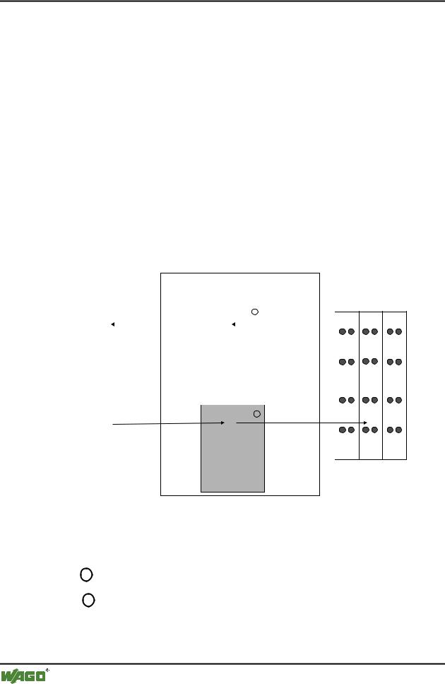
3.1.5.2 Memory Areas
The Coupler uses a memory space of 256 words (word 0 ... 255) for the physical input and output data.
The division of the memory spaces is identical with all WAGO fieldbus Couplers.
fieldbus coupler
fieldbus |
memory area |
|
|
||||||
for input data |
|
|
|||||||
|
|
|
|
word 0 |
|
|
|
||
|
|
|
|
1 |
|
|
|
||
|
|
|
|
|
|
|
|
|
|
|
|
|
|
|
input |
|
|
|
|
|
|
|
|
modules |
|
|
|
||
|
|
|
|
word 255 |
|
|
|
||
|
|
|
|
memory area |
|
|
|||
|
|
|
|
for output data |
|
|
|||
|
|
|
|
word 0 |
|
|
|||
|
|
|
|
2 |
|
|
|
||
|
|
|
|
|
output |
|
|
||
|
|
|
|
modules |
|
|
|||
|
|
|
|
|
|
|
|
|
|
I/O modules
I O
word 255 |
|
Fig. 3-9: Memory areas and data exchange for a fieldbus Coupler |
g012433e |
The Coupler process image contains the physical data of the bus modules in a storage area for input data and in a storage area for output data (word 0 ... 255 each).
1The input module data can be read from the fieldbus side.
2In the same manner, writing to the output modules is possible from the fieldbus side.
WAGO-I/O-SYSTEM 750
DeviceNet