
Common MODBUS functions • 283
Function code FC1 (Read Coils)
6.2.1Function code FC1 (Read Coils)
The function reads the status of the input and output bits (coils) in slave.
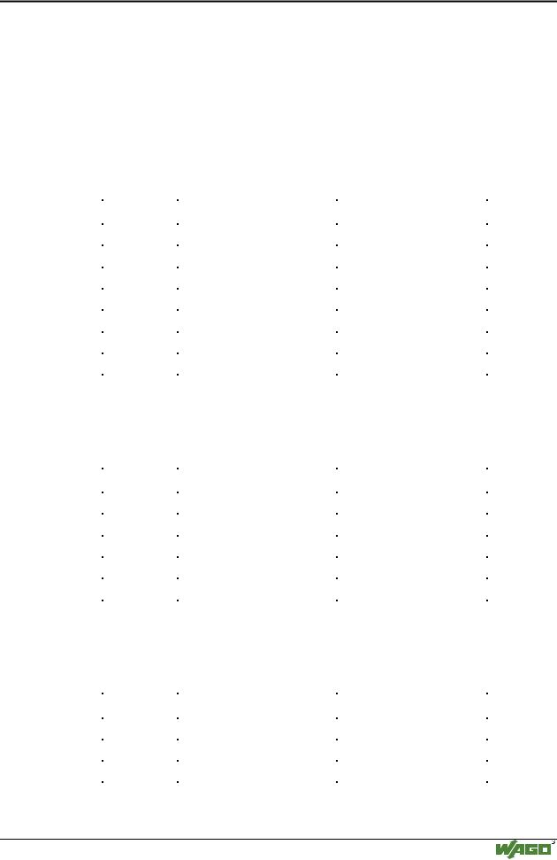
Request
The request determines the starting address and the number of bits to be read. Example: An inquiry, with which the bits 0 to 7 are to be read.
Byte |
Field name |
Example |
Byte 0, 1 |
Transaction identifier |
0x0000 |
|
|
|
Byte 2, 3 |
protocol identifier |
0x0000 |
|
|
|
Byte 4, 5 |
length field |
0x0006 |
|
|
|
Byte 6 |
unit identifier |
0x01 not used |
|
|
|
Byte 7 |
MODBUS function code |
0x01 |
|
|
|
Byte 8, 9 |
reference number |
0x0000 |
|
|
|
Byte 10, 11 |
Bit count |
0x0008 |
|
|
|
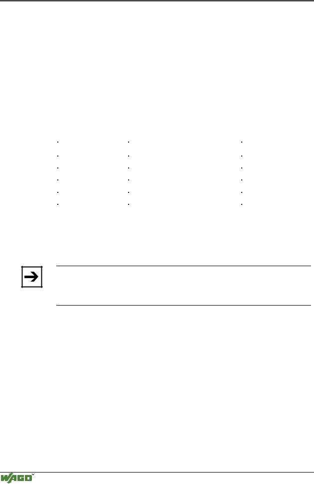
Response
The current values of the inquired bits are packed in the data field. A 1 corresponds to the ON status and a 0 to the OFF status. The lowest value bit of the first data byte contains the first bit of the inquiry. The others follow in ascending order. If the number of inputs is not a multiple of 8, the remaining bits of the last data byte are filled with zeroes (truncated).
Byte |
Field name |
Example |
..... |
|
|
|
|
|
Byte 7 |
MODBUS function code |
0x01 |
|
|
|
Byte 8 |
Byte count |
0x01 |
|
|
|
Byte 9 |
Bit values |
0x12 |
|
|
|
The status of the inputs 7 to 0 is shown as byte value 0x12 or binary 0001 0010.
Input 7 is the bit having the highest significance of this byte and input 0 the lowest value.
The assignment is thus made from 7 to 0 with OFF-OFF-OFF-ON-OFF-OFF-
ON-OFF. |
|
|
|
|
|
|
|
|
|
Bit: |
0 |
0 |
0 |
1 |
0 |
0 |
1 |
0 |
|
Coil: |
7 |
6 |
5 |
4 |
3 |
2 |
1 |
0 |
|
Exception |
|
|
|
|
|
|
|
|
|
|
|
|
|
|
|
|
|||
Byte |
|
Field name |
|
|
|
Example |
|||
..... |
|
|
|
|
|
|
|
|
|
|
|
|
|
||||||
Byte 7 |
|
MODBUS function code |
0x81 |
||||||
|
|
|
|
|
|
|
|||
Byte 8 |
|
Exception code |
|
|
|
0x01 or 0x02 |
|||
|
|
|
|
|
|
|
|
|
|
Modular I/O System
ETHERNET TCP/IP
284 • Common MODBUS functions Function code FC2 (Read Discrete Inputs)
6.2.2Function code FC2 (Read Discrete Inputs)
This function reads the input bits in the slave.
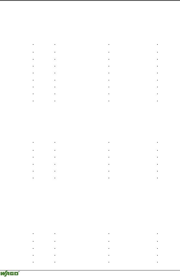
Requests
The request determines the starting address and the number of bits to be read. Example: An inquiry with which the bits 0 to 7 are to be read:
Byte |
Field name |
Example |
Byte 0, 1 |
Transaction identifier |
0x0000 |
|
|
|
Byte 2, 3 |
protocol identifier |
0x0000 |
|
|
|
Byte 4, 5 |
Length field |
0x0006 |
|
|
|
Byte 6 |
unit identifier |
0x01 not used |
|
|
|
Byte 7 |
MODBUS function code |
0x02 |
|
|
|
Byte 8, 9 |
reference number |
0x0000 |
|
|
|
Byte 10, 11 |
Bit count |
0x0008 |
|
|
|
Response
The current value of the inquired bit is packed into the data field. A 1 corresponds to the ON status and a 0 the OFF status. The lowest value bit of the first data byte contains the first bit of the inquiry. The others follow in an ascending order. If the number of inputs is not a multiple of 8, the remaining bits of the last data byte are filled with zeroes (truncated).
Byte |
Field name |
Example |
..... |
|
|
|
|
|
Byte 7 |
MODBUS function code |
0x02 |
|
|
|
Byte 8 |
Byte count |
0x01 |
|
|
|
Byte 9 |
Bit values |
0x12 |
|
|
|
The status of the inputs 7 to 0 is shown as a byte value 0x12 or binary 0001 0010.
Input 7 is the bit having the highest significance of this byte and input 0 the lowest value.
The assignment is thus made from 7 to 0 with OFF-OFF-OFF-ON-OFF-OFF-
ON-OFF. |
|
|
|
|
|
|
|
|
|
Bit: |
0 |
0 |
0 |
1 |
0 |
0 |
1 |
0 |
|
Coil: |
7 |
6 |
5 |
4 |
3 |
2 |
1 |
0 |
|
Exception |
|
|
|
|
|
|
|
|
|
|
|
|
|
|
|
|
|||
Byte |
|
Field name |
|
|
|
Example |
|||
..... |
|
|
|
|
|
|
|
|
|
|
|
|
|
||||||
Byte 7 |
|
MODBUS function code |
0x82 |
||||||
|
|
|
|
|
|
|
|||
Byte 8 |
|
Exception code |
|
|
|
0x01 or 0x02 |
|||
|
|
|
|
|
|
|
|
|
|
Modular I/O System
ETHERNET TCP/IP