

- •TABLE OF CONTENTS
- •Important comments
- •Legal principles
- •Copyright
- •Personnel qualification
- •Intended use
- •Scope
- •Symbols
- •Font conventions
- •Number notation
- •Abbreviation
- •The WAGO-I/O-SYSTEM 750
- •System Description
- •General
- •Coupler/Controller (1)
- •I/O Modules (2)
- •End Module (3)
- •Installation
- •Safty notes
- •Mechanical Installation
- •Electrical Installation
- •Wire Connection
- •Change fuse
- •Power supply
- •System supply voltage
- •Supply Voltage Field Side
- •Manufacturing Number
- •Technical Data
- •Fieldbus coupler / controller
- •Fieldbus coupler 750-342
- •Description
- •Hardware
- •View
- •Device supply
- •Fieldbus connection
- •Display elements
- •Configuration interface
- •Operating system
- •Process image
- •Example of a process input image
- •Example of a process output image
- •Process data architecture for MODBUS/TCP
- •Data exchange
- •Memory areas
- •Addressing
- •Data exchange between MODBUS master and I/O modules
- •Starting up ETHERNET TCP/IP fieldbus nodes
- •Connecting PC and fieldbus node
- •Determining IP addresses
- •Allocating the IP address to the fieldbus node
- •Testing the function of the fieldbus node
- •Reading out the information as HTML pages
- •LED Display
- •Blink code
- •Fieldbus status
- •Node status
- •Fault behavior
- •Fieldbus failure
- •Internal bus fault
- •Technical Data
- •Fieldbus controller 750-842
- •Description
- •Hardware
- •View
- •Device supply
- •Fieldbus connection
- •Display elements
- •Configuration and programming interface
- •Operating mode switch
- •Operating system
- •Start-up
- •PLC cycle
- •Process image
- •Example of a process input image
- •Example of a process output image
- •Process data architecture for MODBUS/TCP
- •Data exchange
- •Memory areas
- •Addressing
- •Data exchange between master and I/O modules
- •Data exchange between PLC functionality (CPU) and I/O modules
- •Data exchange between master and PLC functionality (CPU)
- •Common access of MODBUS master and PLC functionality to outputs
- •Address review
- •Starting up ETHERNET TCP/IP fieldbus nodes
- •Connecting PC and fieldbus node
- •Determining IP addresses
- •Allocating the IP address to the fieldbus node
- •Testing the function of the fieldbus node
- •Viewing the HTML pages
- •Programming the PFC with WAGO-I/O-PRO 32
- •LED Display
- •Blink code
- •Fieldbus status
- •Node status
- •Supply voltage status
- •Fault behavior
- •Fieldbus failure
- •Internal bus fault
- •Technical Data
- •I/O modules
- •I/O modules-Review
- •Digital Inputs
- •Digital Outputs
- •Analog Inputs
- •Analog Outputs
- •Supply and End modules
- •Terminal blocks for encoder and resolvers
- •Special terminal blocks
- •ETHERNET
- •Network architecture – Principles and Regulations
- •Transmission media
- •Network topologies
- •Coupler modules
- •Important terms
- •Network communication
- •Channel access method
- •Communication protocols
- •ETHERNET
- •IP-Protocol
- •TCP protocol
- •ICMP
- •Application protocols
- •MODBUS/TCP
- •Bootstrap Protocol (BootP)
- •HyperText Transfer Protocol (HTTP)
- •Common MODBUS functions
- •Use of the MODBUS functions
- •Description of the MODBUS functions
- •Function code FC1 (Read Coils)
- •Function code FC2 (Read Discrete Inputs)
- •Function code FC3 (Read multiple registers)
- •Function code FC4 (Read input registers)
- •Function code FC5 (Write Coil)
- •Function code FC6 (Write single register)
- •Function code FC7 (Read Exception Status)
- •Function code FC16 (Write multiple registers)
- •Function code FC11 (Get comm event counter)
- •Function code FC23 (Read/Write multiple registers)
- •Watchdog (Fieldbus failure)
- •Diagnostic function
- •Configuration function
- •Firmware information
- •General Registers
- •Special PFC Register (only for controller 750-842)
- •Application examples
- •Test of MODBUS protocol and fieldbus nodes
- •Visualization and control using SCADA software
- •Application in Explosive Environments
- •Foreword
- •Protective measures
- •Classification meeting CENELEC and IEC
- •Divisions
- •Explosion protection group
- •Unit categories
- •Temperature classes
- •Types of ignition protection
- •Classifications meeting the NEC 500
- •Divisions
- •Explosion protection groups
- •Temperature classes
- •Identification
- •For Europe
- •For America
- •Installation regulations
- •Glossary
- •Literature list
- •Index

238 • I/O modules
Special terminal blocks - Review
4.8 Special terminal blocks
750-650 (RS232 C9600, n, 8, 1)
page 239
750-651 (TTY-, 20 mA Current Loop)
page 245
750-653 (RS485 Interface)
page 251
750-654 (Data exchange module)
page 257
Modular I/O System
ETHERNET TCP/IP

I/O modules • 239
RS232C interface 750-650
4.8.1.1.1 RS232C Interface
750-650
|
13 |
14 |
|
Function |
A |
|
|
|
C |
|
|
TxD |
B |
|
RxD |
|
D |
||
|
TxD RxD |
Data contacts |
|
|
|
|
|
TxD |
|
|
RxD |
|
RTSCTS |
|
|
RTS |
|
|
CTS |
|
M |
M |
|
Common |
|
|
Common |
(ground) |
|
|
(ground) |
|
S |
S |
|
Shield |
|
|
Shield |
(screen) |
|
|
(screen) |
|
750-650 |
|
|
I/O modules and variations
Item-No.: Description
750-650 |
RS 232 C Interface 9600,n,8,1 |
750-650/000-001 RS 232 C Interface 9600,n,8,1
5 Byte
Name
RS 232 C/ 9600/ N/ 8/ 1
RS 232 C/ 9600/ N/ 8/ 1/ 5BYTE
Technical description
This technical description is only valid for hardware and software versions X X X X 2 C 0 3----. The product series number is printed on the right side of the module.
The following description is preliminary and is applicable to the factory preset configuration.
Many other operational modes are possible (please contact WAGO for the corresponding settings).
The interface module can operate with all WAGO-I/O-SYSTEM buscouplers (except for the economy type).
Modular I/O System
ETHERNET TCP/IP

240 • I/O modules
RS232C interface 750-650
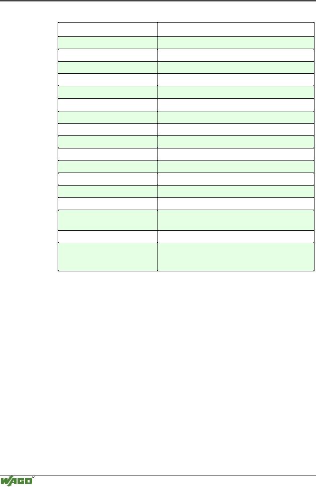
Technical Data:
Item-No.:
Transmission channel
Transmission rate
Bit skew
Bit transmission
Resistance
Current consumption (internal)
Transmission length
Input buffer
Output buffer
Voltage supply
Isolation
Internal bit width
Configuration
Operating temperature
Wire connection
Dimensions (mm) WxHxL
Presetting:
Baud rate
Internal bit width
750-650,
750-650/000-001
2 (1/1), T x D and R x D, full duplex
1200 - 19200 Baud
< 3 %
-
-
50 mA max.
max. 15 m RS 232 cable
128 Byte
16 Byte
via internal system supply
500 V System/power supply
1 x 40 Bit, 1 x 8 Bit control/status
none, or via software with the consent of WAGO
0 °C ... + 55 °C
CAGE CLAMP ; 0.08 mm2 - 2.5 mm2, AWG 28 – 14, 8 – 9 mm Stripped length
12 x 64* x 100 (*from upper edge of carrier rail)
9600 Baud
1 x 24 Bit in/out, 1 x 8 Bit Control/Status
Description of RS 232:
The interface module is designed to operate with all WAGO I/O fieldbus couplers. The serial interface module allows the connection of RS 232-Interface devices to the WAGO I/O SYSTEM. The RS 232 Interface module can provide gateways within the fieldbus protocol. This allows serial equipment such as printers, barcode readers, and links to local operator interfaces to communicate directly by the fieldbus protocol with the PLC or PC Master.
This module does not support a higher level protocol. Communication is made completely transparent to the fieldbus allowing flexibility in further applications of the serial interface module. The communication protocols are configured at the Master PLC or PC.
The 128 byte input buffer provides for high rates of data transmission. When using slower transmission speeds, you can collect the received data with lower priority without loosing data.
The 16 byte output buffer provides for faster transmission of larger data strings.
Modular I/O System
ETHERNET TCP/IP

I/O modules • 241
RS232C interface 750-650
Attention
The data transmission takes place at 9,600 baud (default value). 1 start bit, 8 data bits and 1 stop bit will be transmitted. No parity is available. The user controls data via the RTS and CTS signals. These signals are generated in the module depending on the loading status of the buffers. These controls can be deactivated by means of an external jumper. RTS and CTS are to be connected.
Attention
For testing purposes the Windows terminal emulation  can be used. A cable with a 9- pole sub-D socket is required. Pin 5 is connected to input "common". Pin 2 is connected to TxD and Pin 3 to RxD. RTS and CTS of the module are connected. A hardwarehandshake between the terminal emulation and the PLC is not possible.
Organization of the inand output data:
The module is a combined analog input and output module with 2 x 16 bit input and output data. The transfer of the data to be transmitted and the received data is made via 3 output and 3 input bytes. One control byte and one status byte are used to control the floating data.
Requests are indicated by a change of a bit. An assigned bit indicates execution by adopting the value of the request bit.
Up to 3 characters which have been received via interface can be stored in the input bytes 0 to 2. The output bytes will contain the characters to be sent.
The control byte consists of the following bits:
Bit 7
0
Constant value should always be 0.
Bit 6 |
Bit 5 |
Bit 4 |
OL 2 |
OL1 |
OL0 |
Frames available in output area OL2 is always 0,
i.e. OL2, OL1, OL0 = 0,1,1
3 characters should be sent and put into the output.
Bit 3 |
Bit 2 |
Bit 1 |
Bit 0 |
0 |
IR |
RA |
TR |
Constant |
Initialization |
Receive |
Transmit |
value |
request |
acknow- |
request |
should |
|
ledge |
|
always |
|
|
|
be 0. |
|
|
|
|
|
|
|
The status byte has the following bits:
Bit 7
0
Constant value should always be 0.
Bit 6 |
Bit 5 |
|
Bit 4 |
Bit 3 |
Bit 2 |
Bit 1 |
Bit 0 |
IL2 |
IL1 |
|
Il0 |
BUF_F |
IA |
RR |
TA |
Frames available in input area |
Input |
Initialization |
Receive |
Transmit |
|||
|
IL2 is always 0. |
|
buffer is |
acknowledge |
request |
acknow- |
|
i.e. IL2, IL1, IL0 = 0,1,0 |
full. |
|
|
ledge |
|||
2 characters were received and |
|
|
|
|
|||
reside in input 0 and input 1. |
|
|
|
|
|||
The PLC/PC is able to control transmission and reception of data by means of the control byte and the status byte.
Modular I/O System
ETHERNET TCP/IP

242 • I/O modules
RS232C interface 750-650
Initialization of the module:
•set IR bit in the control byte to "1"
•transmit/receive functions are blocked
•output/input buffers are erased
•serial interface module will load its configuration data
Transmitting data:
•TR≠ TA: put characters into output bytes 0 to 2
•amount of characters is specified in OL0 to OL2
•TR is inverted and read out
•characters are put into output buffer if TR=TA
Receiving data:
•RR≠ RA: data in input bytes 0 to 2 characters are available
•amount of characters is specified in IL0 to IL2
•characters in IL0 to IL2 are read out
•RA is inverted and read out
•all characters are read when RR=RA
The transmitting and receiving of data can be done simultaneously. The initialization request has priority and will stop transmitting and receiving of data immediately.
Attention
Resetting the initialization bit can be performed with the following message.
Message: input buffer full (Bit 3)
Input buffer is full. Data which is being currently received is now lost.
Modular I/O System
ETHERNET TCP/IP

I/O modules • 243
RS232C interface 750-650
An example:
The module is initialized.
- The initialization bit in the control byte is set.
Output byte 0 |
|
Control byte |
Output byte 2 |
Output byte 1 |
0x00 |
|
0000.0100 |
0x00 |
0x00 |
- After the initialization has been executed, the status byte will give back 000.0100.
Input |
Status byte |
Input |
Input |
|
|
|
|
|
|
byte 0 |
|
Byte 2 |
byte 1 |
|
XX |
0XXX.X0XX |
XX |
XX |
Module is still being reset. |
XX |
0XXX.X1XX |
XX |
XX |
Initialization completed. |
Sending of the data string "Hello” in ASCII code:
-The first 3 characters and the buffer length of 3 are transmitted.
Output |
|
Control byte |
Output |
Output |
|
byte 0 |
|
|
byte 2 |
byte 1 |
|
|
|
|
|||
‘H’ (0 x 48) |
|
0011.0000 |
‘l’ (0 x 6C) |
‘e’ (0 x 60) |
Entering data to module |
-The transmission request bit (TR) is inverted.
Output |
|
Control byte |
Output |
Output |
|
byte 0 |
|
|
byte 2 |
byte 1 |
|
|
|
|
|||
‘H’ |
|
0011.0001 |
‘l’ |
‘e’ |
Send Data |
-As soon as TR=TA, the rest of the data can be sent.
Input |
Status byte |
Input |
Input |
|
|
|
|
|
|
byte 0 |
|
Byte 2 |
byte 1 |
|
XX |
0XXX.XXX0 |
XX |
XX |
The data is still being trans- |
|
|
|
|
ferred. |
XX |
0XXX.XXX1 |
XX |
XX |
Data transfer completed. |
-The last 2 characters and the buffer length of 2 are transmitted.
Output byte 0 |
|
Control byte |
Output byte 2 |
Output byte 1 |
‘l’ |
|
0010.0001 |
XX |
‘o’ (0 x 6F) |
-The transmission request bit (TR) is inverted.
Output byte 0 |
|
Control byte |
Output byte 2 |
Output byte 1 |
‘l’ |
|
0010.0000 |
XX |
‘o’ |
- As soon as TA = TR, the data has been transferred to the output buffer.
Modular I/O System
ETHERNET TCP/IP
244 • I/O modules
RS232C interface 750-650
|
|
Input |
|
|
Status byte |
|
|
Input |
|
|
|
|
|
|
Input |
|
|
|
|
|
|
byte0 |
|
|
|
|
|
|
|
|
|
|
|
|
|
|
|
|
|
|
|
|
|
|
|
|
|
byte2 |
|
|
|
|
|
|
byte1 |
|
|
|
|
|
|
|
|
|
|
|
|
|
|
|
|
|
|
|
|
|
|
||
|
|
|
|
|
|
|
|
|
|
||||||||||
|
|
XX |
|
|
0XXX.XXX1 |
|
|
XX |
|
|
|
|
XX |
|
The data is still being transferred. |
||||
|
|
XX |
|
|
0XXX.XXX0 |
|
|
XX |
|
|
|
|
|
|
XX |
|
Data transfer completed. |
||
Receiving the character chain "WAGO” |
|
|
|
|
|||||||||||||||
-As soon as RA≠ RR, the input bytes contain data. |
|
||||||||||||||||||
|
|
Output byte 0 |
Control byte |
|
|
|
Output byte 2 |
Output byte 1 |
|||||||||||
|
|
XX |
|
|
|
0XXX.000X |
|
|
|
|
XX |
XX |
|||||||
|
|
|
|
|
|
|
|
|
|
|
|
|
|||||||
|
|
Input |
|
|
Status byte |
|
|
Input |
|
|
|
Input |
|
|
|
||||
|
|
|
|
|
|
|
|
|
|
|
|
|
|
|
|
|
|||
|
|
byte0 |
|
|
|
|
|
|
byte2 |
|
|
|
byte1 |
|
|
|
|||
|
|
XX |
|
|
0XXX.0X0X |
|
|
XX |
|
XX |
|
No received data available. |
|||||||
|
|
‘W’ |
|
|
0011.0X1X |
|
|
‘G’ |
|
‘A’ |
|
The information is in the input |
|||||||
|
|
|
|
|
|
|
|
|
|
|
|
|
|
|
|
|
|
|
bytes. |
-After the 3 characters have been processed, RA is inverted.
Output |
Control |
Output |
Output |
|
byte 0 |
byte |
byte 2 |
byte 1 |
|
XX |
0XXX.001X |
XX |
XX |
Command to read from input |
|
|
|
|
buffer |
-If RA≠ RR, the receiving of additional characters will continue.
Input |
Status byte |
Input |
Input |
|
byte 0 |
|
byte 2 |
byte 1 |
|
|
|
|||
XX |
0XXX.0X1X |
XX |
XX |
No received data available. |
‘O’ |
0001.0X0X |
XX |
XX |
The information is in the input |
|
|
|
|
bytes. |
-After the characters have been processed, RA is inverted.
|
Output byte 0 |
Control byte |
Output byte2 |
Output byte1 |
|
XX |
0XXX.000X |
XX |
XX |
Attention
0 x 23 is a hexadecimal value
0101.1001 is a binary value
An X indicates that this particular value has no importance. XX indicates that the whole value has no importance.
Attention
For the process data configuration of these bus modules please refer to chapter "Process data architecture for MODBUS/TCP" in the process image description of the corresponding coupler/controller.
Modular I/O System
ETHERNET TCP/IP

I/O modules • 245
TTY interface 750-651
4.8.1.1.2 TTY Interface - 20mA Current Loop
750-651
|
13 |
14 |
|
|
Function |
A |
|
|
|
|
C |
|
|
|
TxD |
B |
|
RxD |
|
|
__D |
|
||
|
TxD TxD |
Data contacts |
|
|
|
|
|
Receiver |
|
|
|
|
___ |
|
|
|
|
|
|
|
|
|
TxD |
|
|
|
|
TxD |
|
|
|
__ |
|
Transmitter |
|
RxD RxD |
|
||
|
|
|
||
|
|
|
RxD |
|
|
|
|
___ |
|
|
|
|
RxD |
|
|
750-651 |
|
|
|
Technical description
This technical description is only valid for hardware and software versions X X X X 2 C 0 3----. The product series number is printed on the right side of the module.
The following description is preliminary and is applicable to the factory preset configuration.
Many other operational modes are possible (please contact WAGO for the corresponding settings).
The interface module can operate with all WAGO-I/O-SYSTEM buscouplers (except for the economy type).
Modular I/O System
ETHERNET TCP/IP
246 • I/O modules
TTY interface 750-651
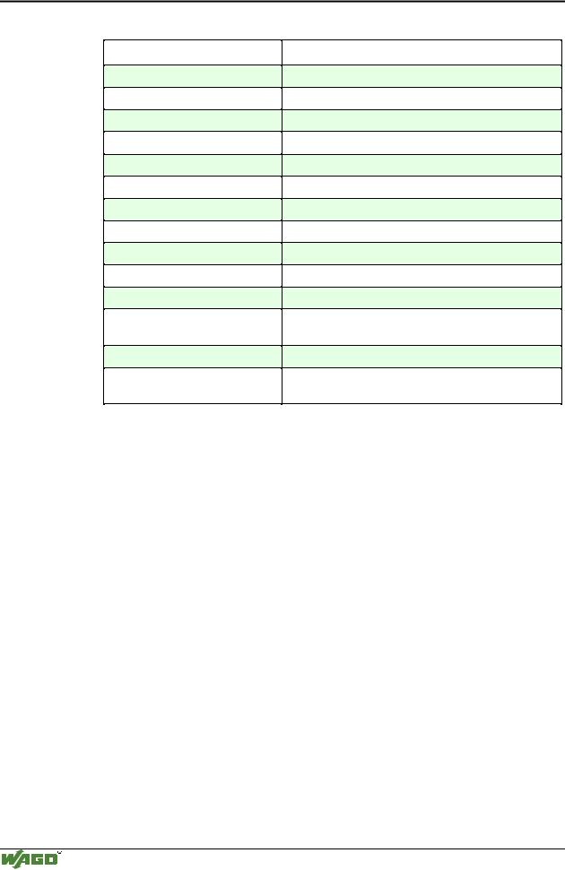
Technical Data:
Item-No.:
Transmission channel
Transmission rate
Bit skew
Bit transmission
Resistance
Current consumption (internal)
Transmission length
Input buffer
Output buffer
Voltage supply
Isolation
Internal bit width
Configuration
Operating temperature
Wire connection
Dimensions (mm) WxHxL
Presetting:
Baud rate
Internal bit width
750-651
2 (1/1), T x D and R x D, full duplex
1200 - 19200 Baud
-
2 x 20 mA passive
< 500 Ω
50 mA max.
max. 1000 m twisted pair
128 Byte
16 Byte
via internal system supply
500 V System/power supply
1 x 40 Bit, 1 x 8 Bit control/status
none, or via software with the consent of WAGO
0 °C ... + 55 °C
CAGE CLAMP ; 0.08 mm2 - 2.5 mm2, AWG 28 – 14, 8 – 9 mm Stripped length
12 x 64* x 100 (*from upper edge of carrier rail)
9600 Baud
1 x 24 Bit in/out, 1 x 8 Bit control/status
Description TTY:
The TTY interface module allows the connection of TTY-Interface devices to the WAGO I/O SYSTEM. The TTY Interface module can provide gateways within the fieldbus protocol. This allows serial equipment such as printers, barcode readers, and links to local operator interfaces to communicate directly by the fieldbus protocol with the PLC or PC Master.
This module does not support a higher level protocol. Communication is made completely transparent to the fieldbus allowing flexibility in further applications of the serial interface module. The communication protocols are configured at the Master PLC or PC.
The 128 byte input buffer provides for high rates of data transmission. When using slower transmission speeds, you can collect the received data with lower priority without loosing data.
The 16 byte output buffer provides for faster transmission of larger data strings.
Modular I/O System
ETHERNET TCP/IP
I/O modules • 247
TTY interface 750-651
Attention
The data transmission takes place at 9600 baud (default value). 1 start bit, 8 data bits and 1 stop bit will be transmitted. No parity is available. The drivers are high impedence. The control of data is made by the user software.
Attention
The TTY Interface is passive in sending and receiving, thus having no current sources. For data conversion, an active partner is needed or an additional current source has to be connected.
Receiver
with current source
 20 mA
20 mA
TxD |
TxD |
|
|
|
|
|
|
TxD |
TxD |
|
||
+ |
- |
|
|
|
+ |
- |
|
|||||
|
|
|
|
|
|
|
|
|
|
|
|
|
|
|
|
|
|
|
|
|
|
|
|
|
|
|
|
|
|
|
|
|
|
|
|
|
|
|
|
|
|
|
|
|
|
|
|
|
|
|
|
|
Transmitter with |
|
current source |
|
20 mA |
RxDRxD |
RxDRxD |
+ - |
+ - |
:$*2 |
:$*2 |
|
|
Current source
20 mA
Receiver
Current source 20 mA
Transmitter
TxD TxD
+-
RxDRxD
+-
:$*2
Current source
20 mA
Receiver
Transmitter
Point to point connection |
Point to point connection with passive |
with active subscribers |
subscriber and additional current sources |
Bus connection with a current source and a passive subscriber
Organization of the input and output data:
The module is a combination of an analog input and output module with 2 x 16 bit input and output data. The transfer of the data to be transmitted and the received data is made via 3 output and 3 input bytes. One control byte and one status byte are used to control the floating data.
Requests are indicated by a bit change of state. An assigned bit indicates execution by adopting the value of the request bit.
Up to 3 characters which have been received via interface can be stored in the input bytes 0 to 2. The output bytes will contain the characters to be sent.
The control byte consists of the following bits:
Bit 7
0
Constant value should always be 0.
Bit 6 |
Bit 5 |
Bit 4 |
OL 2 |
OL1 |
OL0 |
Frames available in output area OL2 is always 0,
i.e. OL2, OL1, OL0 = 0,1,1
3 characters should be sent and put into the output.
Bit 3 |
Bit 2 |
Bit 1 |
Bit 0 |
0 |
IR |
RA |
TR |
Constant |
Initialization |
Receive |
Transmit |
value |
request |
acknow- |
request |
should |
|
ledge |
|
always be |
|
|
|
0. |
|
|
|
|
|
|
|
Modular I/O System
ETHERNET TCP/IP

248 • I/O modules
TTY interface 750-651
The status byte consists of the following bits:
Bit 7 |
Bit 6 |
Bit 5 |
|
Bit 4 |
Bit 3 |
Bit 2 |
Bit 1 |
Bit 0 |
0 |
IL2 |
IL1 |
|
Il0 |
BUF_F |
IA |
RR |
TA |
Constant |
rames available in input area IL2 is |
Input |
Initialization |
Receive |
Transmit |
|||
value should |
|
always 0. |
|
buffer is |
acknow- |
request |
acknow- |
|
always be 0. |
i.e. IL2, IL1, IL0 = 0,1,0 |
full. |
ledge |
|
ledge |
|||
|
2 characters were received and |
|
|
|
|
|||
|
reside in input 0 and input 1. |
|
|
|
|
|||
The PLC is able to control transmission and reception of data by means of the control byte and the status byte.
Initialization of the module:
•set IR bit in the control byte to "1"
•transmit/receive functions are blocked
•output/input buffers are erased
•serial interface module will load its configuration data
Transmitting data:
•TR≠ TA: put characters into output bytes 0 to 2
•amount of characters is specified in OL0 to OL2
•TR is inverted and read out
•characters are put into output buffer if TR=TA
Receiving data:
•RR≠ RA: input bytes 0 to 2 characters are available
•amount of characters is specified in IL0 to IL2
•characters in IL0 to IL2 are read out
•RA is inverted and read out
•all characters are read when RR=RA
The transmitting and receiving of data can be done simultaneously. The initialization request has prioirity and will stop the transmitting and receiving of data immediately.
Attention
Resetting the initialization bit can be performed with the following message.
Message: input buffer full (Bit 3)
Input buffer is full. Data which is being currently received is now lost.
Modular I/O System
ETHERNET TCP/IP

I/O modules • 249
TTY interface 750-651
An example:
The module is initialized.
- The initialization bit in the control byte is set.
Output byte 0 |
|
Control byte |
Output byte 2 |
Output byte 1 |
0x00 |
|
0000.0100 |
0x00 |
0x00 |
- After the initialization has been executed, the status byte will give back 000.0100.
Input |
Status byte |
Input |
Input |
|
|
|
|
|
|
byte 0 |
|
byte 2 |
byte 1 |
|
XX |
0XXX.X0XX |
XX |
XX |
Module is still being reset. |
XX |
0XXX.X1XX |
XX |
XX |
Initialization completed. |
Sending of the data string "Hello” in ASCII code:
-The first 3 characters and the buffer length of 3 are transmitted.
Output |
|
Control |
Output |
Output |
|
byte 0 |
|
byte |
byte 2 |
byte 1 |
|
‘H’ (0 x |
|
0011.0000 |
‘l’ (0 x 6C) |
‘e’ (0 x 60) |
Entering data to module |
-The transmission request bit (TR) is inverted.
|
|
Output |
|
|
Control |
|
|
Output |
|
|
|
Output |
|
|
|
|
|
byte 0 |
|
|
byte |
|
|
byte 2 |
|
|
|
byte 1 |
|
|
|
|
|
‘H’ |
|
|
0011.0001 |
|
|
‘l’ |
|
|
|
‘e’ |
|
|
Send Data |
-As soon as TR=TA, the rest of the data can be sent |
|||||||||||||||
|
|
|
|
|
|
|
|
|
|
|
|
|
|
|
|
|
|
Input |
|
|
Status byte |
|
|
Input |
|
|
|
Input |
|
|
|
|
|
|
|
|
|
|
|
|
|
|
|
|
|
|
|
|
|
byte 0 |
|
|
|
|
|
byte 2 |
|
|
|
byte 1 |
|
|
|
|
|
XX |
|
|
0XXX.XXX0 |
|
|
XX |
|
|
|
XX |
|
|
The data is still being transferred. |
|
|
XX |
|
|
0XXX.XXX1 |
|
|
XX |
|
|
|
XX |
|
|
Data transfer completed. |
-The last 2 characters and the buffer length of 2 are transmitted.
Output byte 0 |
|
Control byte |
Output byte 2 |
Output byte 1 |
‘l’ |
|
0010.0001 |
XX |
‘o’ (0 x 6F) |
-The transmission request bit (TR) is inverted.
Output byte 0 |
|
Control byte |
Output byte 2 |
Output byte 1 |
‘l’ |
|
0010.0000 |
XX |
‘o’ |
Modular I/O System
ETHERNET TCP/IP

250 • I/O modules
TTY interface 750-651
- As soon as TA = TR, the data has been transferred to the output buffer.
|
|
Input |
|
|
|
Status byte |
|
|
Input |
|
|
|
Input |
|
|
|
|
|
byte0 |
|
|
|
|
|
|
|
|
|
|
|
|
|
|
|
|
|
|
|
|
|
|
|
byte2 |
|
|
|
byte1 |
|
|
|
|
|
|
|
|
|
|
|
|
|
|
|
|
|
|
||
|
|
|
|
|
|
|
|
|
|
|||||||
|
|
XX |
|
0XXX.XXX1 |
|
|
XX |
|
|
|
XX |
The data is still being transferred. |
||||
|
|
XX |
|
|
|
0XXX.XXX0 |
|
|
XX |
|
|
|
XX |
Data transfer completed. |
||
Receiving the character chain "WAGO” |
|
|
||||||||||||||
-As soon as RA≠ RR, the input bytes contain data. |
|
|||||||||||||||
|
|
Output byte 0 |
Control byte |
|
|
|
Output byte 2 |
Output byte 1 |
||||||||
|
|
XX |
|
0XXX.000X |
|
|
|
|
XX |
XX |
||||||
|
|
|
|
|
|
|
|
|
|
|
|
|
||||
|
|
Input |
Status |
|
|
Input |
|
|
|
Input |
|
|
||||
|
|
|
|
|
|
|
byte |
|
|
|
|
|
|
|
|
|
|
|
byte0 |
|
|
|
byte2 |
|
|
|
byte1 |
|
|
||||
|
|
|
|
|
|
|
|
|
|
|
||||||
|
|
|
|
|
|
|
|
|
|
|
||||||
|
|
XX |
0XXX.0X0X |
|
|
XX |
|
|
|
XX |
No received data available. |
|||||
|
|
‘W’ |
0011.0X1X |
|
|
‘G’ |
|
|
|
‘A’ |
The information is in the input |
|||||
|
|
|
|
|
|
|
|
|
|
|
|
|
|
|
|
bytes. |
-After the 3 characters have been processed, RA is inverted.
Output |
Control |
Output |
Output |
|
byte 0 |
byte |
byte 2 |
byte 1 |
|
XX |
0XXX.001X |
XX |
XX |
Command to read from input buf- |
|
|
|
|
fer |
-If RA≠ RR, the receiving of additional characters will continue.
Input |
Status |
Input |
Input |
|
byte 0 |
byte |
byte 2 |
byte 1 |
|
XX |
0XXX.0X1X |
XX |
XX |
No received data available. |
‘O’ |
0001.0X0X |
XX |
XX |
The information is in the input |
|
|
|
|
bytes. |
-After the characters have been processed, RA is inverted.
Output byte 0 |
Control byte |
Output byte2 |
Output byte1 |
XX |
0XXX.000X |
XX |
XX |
Attention
0 x 23 is a hexadecimal value
0101.1001 is a binary value
An X indicates that this particular value has no importance. XX indicates that the whole value has no importance.
Attention
For the process data configuration of these bus modules please refer to chapter "Process data architecture for MODBUS/TCP" in the process image description of the corresponding coupler/controller.
Modular I/O System
ETHERNET TCP/IP

I/O modules • 251
RS485C interface 750-653
4.8.1.1.3 RS485C Interface
750-653
|
13 |
14 |
|
Function |
A |
|
|
|
C |
|
|
TxD |
B |
|
RxD |
|
__D |
||
|
TxD TxD |
Data contacts |
|
|
|
|
|
|
|
|
___ |
TxD |
|
__ |
TxD |
|
|
|
|
|
RxD RxD |
|
|
|
|
|
___ |
RxD |
|
|
RxD |
|
M |
M |
|
Common |
|
|
Common |
(ground) |
|
|
(ground) |
|
S |
S |
|
Shield |
|
|
Shield |
(screen) |
|
|
(screen) |
|
750-653 |
|
|
Technical description
This technical description is only valid for hardware and software versions X X X X 2 C 0 3----. The product series number is printed on the right side of the module.
The following description is preliminary and is applicable to the factory preset configuration.
Many other operational modes are possible (please contact WAGO for the corresponding settings).
The interface module can operate with all WAGO-I/O-SYSTEM buscouplers (except for the economy type).
Modular I/O System
ETHERNET TCP/IP

252 • I/O modules RS485C interface 750-653
Technical Data:
Item-No.:
Transmission channel
Transmission rate
Bit skew
Bit transmission
Resistance
Input current (internal)
Transmission length
Input buffer
Output buffer
Voltage supply
Isolation
Internal bit width
Configuration
Operating temperature
Wire connection
Dimensions (mm) WxHxL
Presetting:
Baud rate
Internal bit width
750-653
1 TxD / 1 RxD, full/ half duplex
1200 - 19200 Baud
-
Acc. to ISO 8482/ DIN 66259 T 4
-
50 mA max.
max. 500 m twisted pair
128 Byte
16 Byte
via internal system supply
500 V System/power supply
1 x 40 Bit, 1 x 8 Bit control/status
none, or via software with the consent of WAGO
0 °C ... + 55 °C
CAGE CLAMP ; 0.08 mm2 - 2.5 mm2, AWG 28 – 14, 8 – 9 mm Stripped length
12 x 64* x 100 (*from upper edge of carrier rail)
9600 Baud
1 x 24 Bit in/out, 1 x 8 Bit control/status
Description RS 485:
The interface module is designed to operate with all WAGO I/O fieldbus couplers. The serial interface module allows the connection of RS485 or RS488Interface devices to the WAGO I/O SYSTEM. The RS485/RS488 Interface module can provide gateways within the fieldbus protocol. This allows serial equipment such as printers, barcode readers, and links to local operator interfaces to communicate directly by the fieldbus protocol with the PLC or PC Master.
This module does not support a higher level protocol. Communication is made completely transparent to the fieldbus allowing flexibility in further applications of the serial interface module. The communication protocols are configured at the Master PLC or PC.
The 128 byte input buffer provides for high rates of data transmission. When using slower transmission speeds, you can collect the received data with less priority without loosing data.
Modular I/O System
ETHERNET TCP/IP

I/O modules • 253
RS485C interface 750-653
The 16 byte output buffer provides for faster transmission of larger data strings.
Attention
The data transmission takes place at 9,600 baud (default value). 1 start bit, 8 data bits and 1 stop bit will be transmitted. No parity is available. The drivers are high impedence. The control of data is made by the user software.
Attention
The interface module can be used for bus connections as well as for point to point connections. With bus connections, modules that are not connected to the power supply can also be wired. They do not disturb the bus connection.
receiver
termination
TxDTxD
+-
RxDRxD |
transmitter |
+ - |
M M |
S S
:$*2
TxD TxD |
|
termination |
|
+ |
- |
|
|
RxDRxD |
|
|
|
+ |
- |
|
|
|
transmitter and |
transmitter nd |
transmitter and |
|
receiver |
receiver |
receiver |
M M |
S 
 S
S
:$*2
point to point connection |
bus connection |
Organization of the input and output data:
The module is a combination of analog input and output module with 2 x 16 bit input and output data. The transfer of the data to be transmitted and the received data is made via 3 output and 3 input bytes. One control byte and one status byte are used to control the floating data.
Requests are indicated by a bit change of state. An assigned bit indicates execution by adopting the value of the request bit.
Up to 3 characters which have been received via interface can be stored in the input bytes 0 to 2. The output bytes will contain the characters to be sent.
Modular I/O System
ETHERNET TCP/IP

254 • I/O modules RS485C interface 750-653
The control byte consists of the following bits:
Bit 7 |
Bit 6 |
|
Bit 5 |
|
Bit 4 |
Bit 3 |
Bit 2 |
Bit 1 |
Bit 0 |
0 |
OL 2 |
|
OL1 |
|
OL0 |
0 |
IR |
RA |
TR |
Constant |
Frames available in output area |
Constant |
Initialization |
Receive |
Transmit |
||||
value |
|
OL2 is always 0, |
|
value |
request |
acknow- |
request |
||
should |
i.e. OL2, OL1, OL0 = 0,1,1 |
should |
|
ledge |
|
||||
lways be 0. |
3 characters should be sent and put |
always be |
|
|
|
||||
|
|
into the output. |
|
0. |
|
|
|
||
|
|
|
|
|
|
|
|||
The status byte consists of the following bits:
Bit 7 |
Bit 6 |
Bit 5 |
Bit 4 |
Bit 3 |
Bit 2 |
Bit 1 |
Bit 0 |
0
Constant value should always be 0.
IL2 |
IL1 |
Il0 |
BUF_F |
IA |
RR |
TA |
Frames available in input area IL2 is |
Inpput |
Initialization |
Receive |
Transmit |
||
|
always 0. |
|
buffer is |
acknow- |
request |
acknow- |
i.e. IL2, IL1, IL0 = 0,1,0 |
full. |
ledge |
|
ledge |
||
2 characters were received and |
|
|
|
|
||
reside in input 0 and input 1. |
|
|
|
|
||
The PLC is able to control transmission and reception of data by means of the control byte and the status byte.
Initialization of the module:
•set IR bit in the control byte to "1"
•transmit/receive functions are blocked
•output/input buffers are erased
•serial interface module will load its configuration data
Transmitting data:
•TR≠ TA: put characters into output bytes 0 to 2
•amount of characters is specified in OL0 to OL2
•TR is inverted and read out
•characters are put into output buffer if TR=TA
Receiving data:
•RR≠ RA: input bytes 0 to 2 characters are available
•amount of characters is specified in IL0 to IL2
•characters in IL0 to IL2 are read out
•RA is inverted and read out
•all characters are read when RR=RA
The transmitting and receiving of data can be done simultaneously. The initialization request has prioirity and will stop transmitting and receiving of data immediately.
Attention
Resetting the initialization bit can be performed with the following message.
Message: input buffer full (Bit 3)
Input buffer is full. Data which is being currently received is now lost.
Modular I/O System
ETHERNET TCP/IP

I/O modules • 255
RS485C interface 750-653
An example:
The module is initialized.
- The initialization bit in the control byte is set.
Output byte 0 |
|
Control byte |
Output byte 2 |
Output byte 1 |
0x00 |
|
0000.0100 |
0x00 |
0x00 |
- After the initialization has been executed, the status byte will give back 000.0100.
Input |
Status byte |
Input |
Input |
|
|
|
|
|
|
byte 0 |
|
byte 2 |
byte 1 |
|
XX |
0XXX.X0XX |
XX |
XX |
Module is still being reset. |
XX |
0XXX.X1XX |
XX |
XX |
Initialization completed. |
Sending of the data string "Hello” in ASCII code:
-The first 3 characters and the buffer length of 3 are transmitted.
Out- |
|
Control byte |
Output |
Output |
|
put |
|
|
byte 2 |
byte 1 |
|
|
|
|
|||
byte 0 |
|
|
|
|
|
|
|
|
|
|
|
‘H’ (0 x |
|
0011.0000 |
‘l’ (0 x 6C) |
‘e’ (0 x |
Entering data to module |
-The transmission request bit (TR) is inverted.
Out- |
|
Control byte |
Output |
Output |
|
put |
|
|
byte 2 |
byte 1 |
|
|
|
|
|||
byte 0 |
|
|
|
|
|
|
|
|
|
|
|
‘H’ |
|
0011.0001 |
‘l’ |
‘e’ |
Send Data |
-As soon as TR=TA, the rest of the data can be sent.
Input |
Status byte |
Input |
Input |
|
|
|
|
|
|
byte 0 |
|
byte 2 |
byte 1 |
|
XX |
0XXX.XXX0 |
XX |
XX |
The data is still being transferred |
XX |
0XXX.XXX1 |
XX |
XX |
Data transfer completed. |
-The last 2 characters and the buffer length of 2 are transmitted.
Output byte 0 |
|
Control byte |
Output byte 2 |
Output byte 1 |
‘l’ |
|
0010.0001 |
XX |
‘o’ (0 x 6F) |
-The transmission request bit (TR) is inverted.
Output byte 0 |
|
Control byte |
Output byte 2 |
Output byte 1 |
‘l’ |
|
0010.0000 |
XX |
‘o’ |
Modular I/O System
ETHERNET TCP/IP

256 • I/O modules RS485C interface 750-653
- As soon as TA = TR, the data has been transferred to the output buffer..
|
|
Input |
|
|
Status |
|
|
|
Input |
|
|
|
Input |
|
|
|
||||
|
|
byte0 |
|
|
byte |
|
|
|
|
|
|
|
|
|
|
|
|
|||
|
|
|
|
|
|
|
byte2 |
|
|
|
byte1 |
|
|
|
||||||
|
|
|
|
|
|
|
|
|
|
|
|
|
|
|
|
|
|
|||
|
|
|
|
|
|
|
|
|
|
|
|
|
||||||||
|
|
XX |
|
|
0XXX.XXX1 |
|
|
XX |
|
XX |
|
The data is still being transferred. |
||||||||
|
|
XX |
|
|
0XXX.XXX0 |
|
|
XX |
|
|
|
XX |
|
Data transfer completed. |
||||||
Receiving the character chain "WAGO” |
|
|
|
|||||||||||||||||
-As soon as RA≠ RR, the input bytes contain data. |
|
|||||||||||||||||||
|
|
Output byte 0 |
|
|
|
Control byte |
|
|
Output byte 2 |
Output byte 1 |
||||||||||
|
|
XX |
|
|
|
|
|
|
0XXX.000X |
|
|
|
XX |
XX |
||||||
|
|
|
|
|
|
|
|
|
|
|
|
|
|
|||||||
|
|
Input |
|
|
Status |
|
|
|
Input |
|
|
|
Input |
|
|
|
||||
|
|
|
|
|
byte |
|
|
|
|
|
|
|
|
|
|
|
|
|||
|
|
byte0 |
|
|
|
|
|
byte2 |
|
|
|
byte1 |
|
|
|
|||||
|
|
|
|
|
|
|
|
|
|
|
|
|
|
|
|
|
||||
|
|
|
|
|
|
|
|
|
|
|
|
|
|
|||||||
|
|
XX |
|
|
0XXX.0X0X |
|
|
XX |
|
XX |
|
No received data available. |
||||||||
|
|
‘W’ |
|
|
0011.0X1X |
|
|
|
‘G’ |
|
|
|
‘A’ |
|
The information is in the input bytes. |
|||||
-After the 3 characters have been processed, RA is inverted.
Out- |
Control |
Output |
Output |
|
put |
byte |
byte 2 |
byte 1 |
|
byte 0 |
|
|
|
|
|
|
|
|
|
XX |
0XXX.001X |
XX |
XX |
Command to read from input buffer |
-If RA≠ RR, the receiving of additional characters will continue.
Input |
Status |
Input |
Input |
|
byte 0 |
byte |
byte 2 |
byte 1 |
|
XX |
0XXX.0X1X |
XX |
XX |
No received data available. |
‘O’ |
0001.0X0X |
XX |
XX |
The information is in the input bytes. |
-After the characters have been processed, RA is inverted.
Output byte 0 |
Control byte |
Output byte2 |
Output byte1 |
XX |
0XXX.000X |
XX |
XX |
Attention
0 x 23 is a hexadecimal value
0101.1001 is a binary value
An X indicates that this particular value has no importance. XX indicates that the whole value has no importance.
Attention
For the process data configuration of these bus modules please refer to chapter "Process data architecture for MODBUS/TCP" in the process image description of the corresponding coupler/controller.
Modular I/O System
ETHERNET TCP/IP
I/O modules • 257
Data exchange modules 750-654
4.8.1.1.4 Data exchange module 750-654
|
13 |
14 |
|
Function |
A |
|
|
|
C |
|
|
TxD |
B |
|
RxD |
|
__D |
||
|
TxD TxD |
Data contacts |
|
|
|
|
|
|
|
|
___ |
TxD |
|
__ |
TxD |
|
|
|
|
|
RxD RxD |
|
|
|
|
|
___ |
RxD |
|
|
RxD |
|
M |
M |
|
Common |
|
|
Common |
(ground) |
|
|
(ground) |
|
S |
S |
|
Shield |
|
|
Shield |
(screen) |
|
|
(screen) |
|
750-654 |
|
|
Technical description
This technical description is only valid for hardware and software version X X X X 2 C 0 0 - - - -. The product series number is printed on the right side of the module.
The data exchange module allows the exchange of data between different fieldbus systems.
Two modules are a communication pair that is connected by means of two twisted wire pairs. Each module is part of a fieldbus node.
The data exchange is done in full duplex operation, independent of the fieldbus system used. The data of the output process image of the fieldbus coupler is transmitted to the communication partner. This module then transmits the data to the input process image of its fieldbus coupler and vice versa.
Factory preset transmission is 32 bits of input data and 32 bits of output data. Data transfer time for 32 bits of I/O is about 5 ms.
The LED “Function“ indicates a data exchange with the buscoupler. The status of the data transmission is indicated by the TxD and RxD LEDs.
The data exchange module can operate with all WAGO-I/O-SYSTEM buscouplers (except for the economy type).
Modular I/O System
ETHERNET TCP/IP
258 • I/O modules
Data exchange modules 750-654
Technical Data:
Item-No.:
Transmission channel
Transmission rate
Bit transmission
Resistance of cable
Input current (internal)
Transmission length
Voltage supply
Isolation
Internal bit width
Configuration
Operating temperature
Wire connection
Dimensions (mm) WxHxL
Presetting:
Internal bit width
750-654
TxD and RxD, full duplex, 2 channels
62500 Baud
via 2 twisted pair with differential signals
120 Ω
65 mA max.
max. 100 m twisted pair
via internal system
500 V System/power supply
1 x 40 Bit in-/output data, 1 x 8 Bit Control/Status
none, or via software with the consent of WAGO
0 °C ... + 55 °C
CAGE CLAMP ; 0.08 mm2 - 2.5 mm2, AWG 28 – 14, 8 – 9 mm Stripped length
12 x 64* x 100 (*from upper edge of carrier rail)
1 x 32 Bit in/out, 1 x 8 Bit control/status
Description of data exchange module:
The data exchange module allows for the exchange of 4 (5) bytes between different fieldbus systems via multiplexing of a serial connection. The delay which is caused by the multiplexor is < 5ms. The integrated watchdog function switches all outputs to zero if there is no valid information for more than 200 ms via the multiplex connection.
The 128 bytes input buffer provides for high rates of data transmission. When using slower speeds, you can collect the received data with lower priority without loosing data.
The 16 byte output buffer provides for faster transmission of larger data strings.
The data exchange module is connected peer-to-peer. For the wiring of the serial multiplex connection the RxD and TxD cables are crossed. The following illustrations show the peer-to-peer connection and the internal structure of the data exchange module.
Modular I/O System
ETHERNET TCP/IP

I/O modules • 259 Data exchange modules 750-654
TxD TxD
+-
RxD RxD
+-
TxD TxD
+-
RxD RxD
+-
M |
M |
M |
M |
S S |
S S |
:$*2 |
:$*2 |
|
|
Point to point connection
|
Input byte 0 |
|
Internal |
|
|
|
|
|
|
|
+5V |
||||||||||
|
|
|
|
|
|
|
|
|
|
|
|
|
|
|
|
|
|
10k |
|||
7 |
6 |
5 |
4 |
3 |
2 |
1 |
0 |
control unit |
|
|
|
|
|
|
|
|
|
|
|||
|
|
|
|
|
|
|
|
|
|
|
|
|
|
|
|
|
|
|
|
RxD+ |
|
|
Input byte 1 |
|
|
|
|
|
|
|
|
|
|
|
|
|
|
||||||
|
|
|
|
|
|
|
|
|
|
|
|
|
|
|
RxD- |
||||||
|
|
|
|
|
|
|
|
|
|
|
|
|
|
|
|
|
|
|
|
|
|
7 |
6 |
5 |
4 |
3 |
2 |
1 |
0 |
|
|
|
|
|
|
|
|
|
|
|
10k |
||
|
|
|
|
|
|
|
|
|
|
|
|
|
|
|
|
|
|
|
|||
|
Input byte 2 |
|
|
|
|
|
|
|
|
|
|
|
|
|
|
TxD+ |
|||||
7 |
6 |
5 |
4 |
3 |
2 |
1 |
0 |
|
|
|
|
|
|
|
|
|
|
|
|
|
|
|
|
|
|
|
|
|
|
|
|
|
|
|
|
|
|
|
|
|
|
|
TxD- |
|
Input byte 3 |
|
|
|
|
EN |
|
|
|
|
|
|
|
M |
|||||||
7 |
6 |
5 |
4 |
3 |
2 |
1 |
0 |
|
|
|
|
|
|
|
|
|
|
|
|
|
|
|
|
|
|
|
|
|
|
|
|
|
|
|
|||||||||
|
|
|
|
|
|
|
|
|
|
|
|
|
S |
||||||||
|
|
|
|
|
|
|
|
|
|
|
|
|
|
|
|
|
|
|
|
|
|
|
Input byte 4 |
|
|
|
|
|
|
|
|
|
|
|
|
|
|
||||||
|
|
|
|
|
|
|
|
|
|
|
|
|
|
|
|||||||
|
|
|
|
|
|
|
|
|
|
|
|
|
|
|
|
||||||
|
|
|
|
|
|
|
|
|
|
|
|
|
|
|
|
||||||
7 |
6 |
5 |
4 |
3 |
2 |
1 |
0 |
|
|
|
|
|
|
|
|
|
|
|
|
|
|
Output byte 0
7 6 5 4 3 2 1 0
Output byte 1
7 6 5 4 3 2 1 0
Output byte 2
7 6 5 4 3 2 1 0
Output byte 3
7 6 5 4 3 2 1 0
|
Output byte 4 |
|
|
|
Control byte |
|
|
|
Status byte |
|
|||||||||||||||
7 |
6 |
5 |
4 |
3 |
2 |
1 |
0 |
|
7 |
6 |
5 |
4 |
3 |
2 |
1 |
0 |
|
7 |
6 |
5 |
4 |
3 |
2 |
1 |
0 |
Organization of the input and output data:
The module is a combination of a special function input and output module with 1 x 32 (40) Bit input and output data. The transfer of the data to be transmitted and the received data is made via 5 input and 5 output Bytes. One control byte and one status byte are used to control the floating data.
Modular I/O System
ETHERNET TCP/IP

260 • I/O modules
Data exchange modules 750-654
The control byte consists of the following bits:
Bit 7 |
Bit |
Bit |
Bit 4 |
Bit 3 |
Bit 2 |
Bit 1 |
Bit 0 |
|
6 |
5 |
|
|
|
|
|
0 |
X |
X |
X |
X |
X |
X |
X |
Constant value |
|
|
|
|
|
|
|
always should |
|
|
|
Not used |
|
|
|
be 0. |
|
|
|
|
|
|
|
The status byte consists of the following bits:
Bit7 |
Bit |
Bit |
Bit4 |
Bit3 |
Bit2 |
Bit1 |
Bit0 |
|
6 |
5 |
|
|
|
|
|
|
|
|
|
|
|
||
0 |
X |
X |
RCVT1 |
RCVT2 |
CHK |
OVR |
PAR |
Constant |
|
|
Module is in |
The recei- |
Checksum |
Buffer |
Parity |
value always |
|
|
timeout. |
ver is in |
error. |
overflow |
error or |
should be 0. |
|
|
All output bits |
timeout. |
|
|
wrong |
|
|
|
are set to 0 |
|
|
|
data in a |
|
|
|
(watchdog). |
|
|
|
frame. |
The PLC is able to control transmission and reception of data by means of the control byte and the status byte.
Control of the multiplex connection:
In the process image of the transmitting buscoupler, one Bit is set to "1" for the whole time. As long as this Bit is "1" in the receiving coupler, further input Bits can be evaluated. If the Bit is "0" the multiplex connection has been disrupted. The further Bits are also 0 because of the watchdog.
Control of the multiplex connection with acknowledge:
If the transmitting buscoupler gets an acknowledge from the receiving buscoupler, the received bit must be transfered as an output bit to the process image. The transmission is successful as long as the Bit is "1".
Handshake:
If a serial data exchange should be made with the data exchange module, the handshake can be made via "Toggle Bits". Therefore an input bit and an output bit are reserved. As soon as those bits are different from each other, a request from the opposite module is made. As soon as the request is executed the output bit is toggled
Modular I/O System
ETHERNET TCP/IP