
- •TABLE OF CONTENTS
- •Important comments
- •Legal principles
- •Copyright
- •Personnel qualification
- •Intended use
- •Scope
- •Symbols
- •Font conventions
- •Number notation
- •Abbreviation
- •The WAGO-I/O-SYSTEM 750
- •System Description
- •General
- •Coupler/Controller (1)
- •I/O Modules (2)
- •End Module (3)
- •Installation
- •Safty notes
- •Mechanical Installation
- •Electrical Installation
- •Wire Connection
- •Change fuse
- •Power supply
- •System supply voltage
- •Supply Voltage Field Side
- •Manufacturing Number
- •Technical Data
- •Fieldbus coupler / controller
- •Fieldbus coupler 750-342
- •Description
- •Hardware
- •View
- •Device supply
- •Fieldbus connection
- •Display elements
- •Configuration interface
- •Operating system
- •Process image
- •Example of a process input image
- •Example of a process output image
- •Process data architecture for MODBUS/TCP
- •Data exchange
- •Memory areas
- •Addressing
- •Data exchange between MODBUS master and I/O modules
- •Starting up ETHERNET TCP/IP fieldbus nodes
- •Connecting PC and fieldbus node
- •Determining IP addresses
- •Allocating the IP address to the fieldbus node
- •Testing the function of the fieldbus node
- •Reading out the information as HTML pages
- •LED Display
- •Blink code
- •Fieldbus status
- •Node status
- •Fault behavior
- •Fieldbus failure
- •Internal bus fault
- •Technical Data
- •Fieldbus controller 750-842
- •Description
- •Hardware
- •View
- •Device supply
- •Fieldbus connection
- •Display elements
- •Configuration and programming interface
- •Operating mode switch
- •Operating system
- •Start-up
- •PLC cycle
- •Process image
- •Example of a process input image
- •Example of a process output image
- •Process data architecture for MODBUS/TCP
- •Data exchange
- •Memory areas
- •Addressing
- •Data exchange between master and I/O modules
- •Data exchange between PLC functionality (CPU) and I/O modules
- •Data exchange between master and PLC functionality (CPU)
- •Common access of MODBUS master and PLC functionality to outputs
- •Address review
- •Starting up ETHERNET TCP/IP fieldbus nodes
- •Connecting PC and fieldbus node
- •Determining IP addresses
- •Allocating the IP address to the fieldbus node
- •Testing the function of the fieldbus node
- •Viewing the HTML pages
- •Programming the PFC with WAGO-I/O-PRO 32
- •LED Display
- •Blink code
- •Fieldbus status
- •Node status
- •Supply voltage status
- •Fault behavior
- •Fieldbus failure
- •Internal bus fault
- •Technical Data
- •I/O modules
- •I/O modules-Review
- •Digital Inputs
- •Digital Outputs
- •Analog Inputs
- •Analog Outputs
- •Supply and End modules
- •Terminal blocks for encoder and resolvers
- •Special terminal blocks
- •ETHERNET
- •Network architecture – Principles and Regulations
- •Transmission media
- •Network topologies
- •Coupler modules
- •Important terms
- •Network communication
- •Channel access method
- •Communication protocols
- •ETHERNET
- •IP-Protocol
- •TCP protocol
- •ICMP
- •Application protocols
- •MODBUS/TCP
- •Bootstrap Protocol (BootP)
- •HyperText Transfer Protocol (HTTP)
- •Common MODBUS functions
- •Use of the MODBUS functions
- •Description of the MODBUS functions
- •Function code FC1 (Read Coils)
- •Function code FC2 (Read Discrete Inputs)
- •Function code FC3 (Read multiple registers)
- •Function code FC4 (Read input registers)
- •Function code FC5 (Write Coil)
- •Function code FC6 (Write single register)
- •Function code FC7 (Read Exception Status)
- •Function code FC16 (Write multiple registers)
- •Function code FC11 (Get comm event counter)
- •Function code FC23 (Read/Write multiple registers)
- •Watchdog (Fieldbus failure)
- •Diagnostic function
- •Configuration function
- •Firmware information
- •General Registers
- •Special PFC Register (only for controller 750-842)
- •Application examples
- •Test of MODBUS protocol and fieldbus nodes
- •Visualization and control using SCADA software
- •Application in Explosive Environments
- •Foreword
- •Protective measures
- •Classification meeting CENELEC and IEC
- •Divisions
- •Explosion protection group
- •Unit categories
- •Temperature classes
- •Types of ignition protection
- •Classifications meeting the NEC 500
- •Divisions
- •Explosion protection groups
- •Temperature classes
- •Identification
- •For Europe
- •For America
- •Installation regulations
- •Glossary
- •Literature list
- •Index
82 • Fieldbus controller 750-842
Programming the PFC with WAGO-I/O-PRO 32
3.2.7Programming the PFC with WAGO-I/O-PRO 32
Due to the IEC 61131 programming of the ETHERNET TCP/IP fieldbus controller 750-842 you have the option to use the functionality of a PLC beyond the functions of fieldbus coupler 750-342.
An application program according to IEC 61131-3 is created using the programming tool WAGO-I/O-PRO 32.
This manual, however, does not include a description of how to program with WAGO-I/O-PRO 32. In contrast, the following chapters are to describe the special modules for WAGO-I/O-PRO 32 for you to utilize explicitly for programming the ETHERNET TCP/IP fieldbus controller.
The description also deals with the way of transmitting the IEC 61131-3 program into the controller and loading a suitable communication driver.
More information
i For a detailed description of how to use the software, please refer to the WAGO-I/O-PRO 32 manual (order No.: 759-122 / 000-001).
3.2.7.1WAGO-I/O-PRO 32 library elements for ETHERNET
You are offered various libraries for different IEC 61131-3 programming applications in WAGO-I/O-PRO 32. They contain modules of universal use and can, thereby, facilitate and speed up the creation of your program. As standard, the library ’standard.lib’is available to you.
The libraries described in the following are specifically intended for
ETHERNET projects with WAGO-I/O-PRO 32:
•"ETHERNET. lib"
(contains elements for the ETHERNET fieldbus communication),
•"EtherTCPmodbus.lib"
(contains elements for the MODBUS TCP fieldbus communication) and
•"Internal types for EtherTCPmodbus.lib"
(contains elements for an easier access to the MODBUS/TCP requests und responses).
These libraries are loaded on the WAGO-I/O-PRO CD.
Having integrated these libraries, you have access to their POUs, data types and global variables which can be used in the same manner as those defined by yourself.
More information
i For a detailed description of the POUs and the software operation, please refer to the WAGO-I/O-PRO 32 manual (order No.: 759-122 / 000-001).
Modular I/O System
ETHERNET TCP/IP
Fieldbus controller 750-842 • 83
Programming the PFC with WAGO-I/O-PRO 32
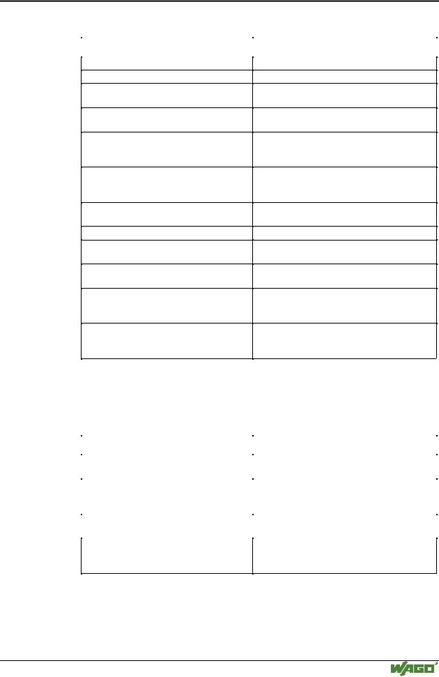
3.2.7.1.1 ETHERNET.lib
Element |
Description |
ETHERNET_CLIENT_CLOSE
ETHERNET_CLIENT_OPEN
ETHERNET_GET_NETWORK_CONFIG
Function block to close a client socket.
Function block to create a client socket. *)
Function block to get the node’s network configuration.
ETHERNET_READ
ETHERNET_SERVER_CLOSE
Function block to read date received from a remote system.
Function block to close a Server socket with all underlying connections (clients connected to the server).
ETHERNET_SERVER_OPEN
ETHERNET_SET_NETWORK_CONFIG
ETHERNET_VERSION
ETHERNET_WRITE
ETH_ERROR (Data type)
SEL_PROTOCOL (Data type)
Function block to create a Server socket. It is a base for a communication to a remote system..*)
Function block to set the node’s network configuration.
Function to get the library’s current version.
Function block to write data to a remote system.
Data type defines the error codes returned by the ETHERNET function blocks.
Data type defines the transport protocol to use. Is used by ETHERNET_CLIENT_OPEN and ETHERNET_SERVER_OPEN.
SEL_TYPE (Data type)
Data type defines the semantics of communication. Is used by ETHERNET_CLIENT_OPEN and ETHERNET_SERVER_OPEN).
*) The maximum number of connections open at a time is 2. You might have to terminate existing connections to ETHERNET_CLIENT_CLOSE or ETHERNET_SERVER_CLOSE.
3.2.7.1.2 EtherTCPmodbus.lib |
|
|
|
|
|
|
Element |
Description |
|
HTONS |
Function converts the value ShortNumber from |
|
|
Intel format to Motorola format. |
|
RECV_MODBUS_MESSAGE |
Function to receive the answer to a |
|
|
MODBUS/TCP request over a TCP connec- |
|
|
tion.*) |
|
SEND_MODBUS_MESSAGE |
Function to send a MODBUS/TCP message |
|
|
over a TCP connection.*) |
MODBUS_FC (Data type)
Data type, defines the function code to use. (Is used by SEND_MODBUS_MESSAGE and RECV_MODBUS_MESSAGE)
*) To prevent a complete filling of the buffer, the module SEND_MODBUS_MESSAGE should always preceed the RECV_MODBUS_MESSAGE.
Modular I/O System
ETHERNET TCP/IP
84 • Fieldbus controller 750-842 Programming the PFC with WAGO-I/O-PRO 32
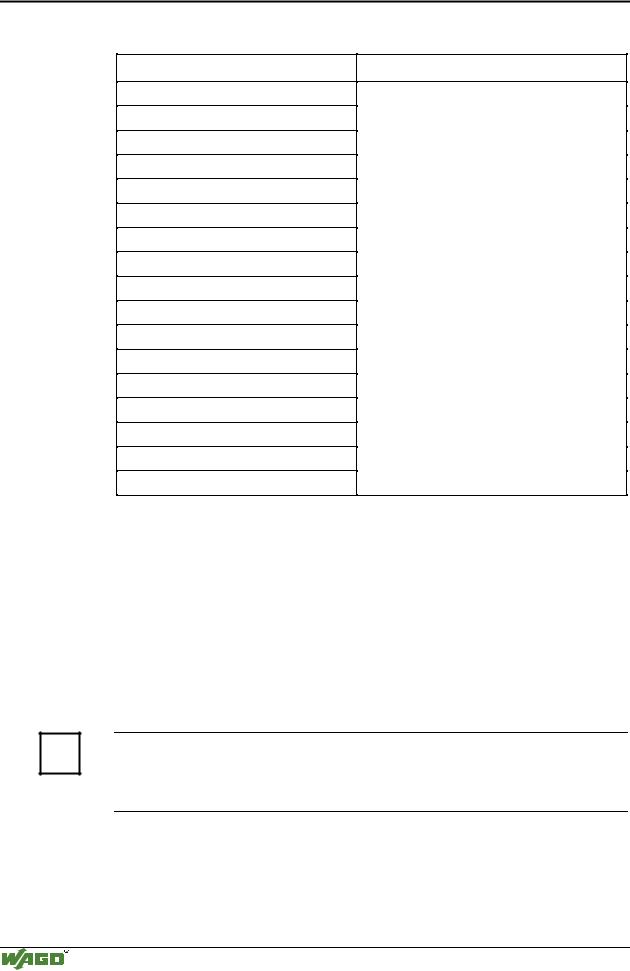
3.2.7.1.3 Internal types for EtherTCPmodbus.lib
Element
MODBUS_HEADER
MODBUS_FMC_REQUEST
MODBUS_FMC_RESPONSE
MODBUS_RC_REQUEST
MODBUS_RC_RESPONSE
MODBUS_RID_REQUEST
MODBUS_RID_RESPONSE
MODBUS_RIR_REQUEST
MODBUS_RIR_RESPONSE
MODBUS_RMR_REQUEST
MODBUS_RMR_RESPONSE
MODBUS_WC_REQUEST
MODBUS_WC_RESPONSE
MODBUS_WMR_REQUEST
MODBUS_WMR_RESPONSE
MODBUS_WSR_REQUEST
MODBUS_WSR_RESPONSE
Description
This types are internally used by the functions SEND_MODBUS_MESSAGE and RECV_MODBUS_MESSAGE. They map the MODBUS/TCP requests and responses, so that an easier access to the message fields can be done.
3.2.7.2IEC 61131-3-Program transfer
Program transfer from the PC to the controller following programming of the desired IEC 61131 application can be made in two different ways:
•via the serial interface or
•via the fieldbus.
One suitable communication driver each is required for both types.
More information
i For information on the installation of the communication drivers as well as details regarding the use of the software, please refer to the WAGO-I/O-PRO 32 manual (order No.: 759-122 / 000-001).
Modular I/O System
ETHERNET TCP/IP
Fieldbus controller 750-842 • 85
Programming the PFC with WAGO-I/O-PRO 32
3.2.7.2.1 Transmission via the serial interface
Use the WAGO communication cable to produce a physical connection to the serial interface. This is contained in the scope of delivery of the programming tool IEC 1131-3, order No.: 759-332/000-002, or can be purchased as an accessory under order No.: 750-920.
Connect the COMX port of your PC with the communication interface of your controller using the WAGO communication cable.
A communication driver is required for serial data transmission. In WAGO-I/O-PRO 32, this driver and its parameterization are entered in the
"Communication parameters" dialog.
1.Start the WAGO-I/O-PRO 32 software by ’Start/Programs’ or by double clicking on the WAGO-I/O-PRO-32 symbol on your desk top.
2.In the "Online" menu click on the "Communication parameters" menu point.
The dialog "Communication parameters" opens. The basic setting of this dialog does not have any entries.
3.In the selection window mark the desired driver on the right-hand dialog side (i.e. "Serial (RS232)", to configure the serial connection between PC and the controller).
4.In the center window of the dialog, the following entries have to appear: - Parity: Even and -Stop bits: 1.
If necessary, change the entries accordingly. You can now begin testing the controller.
Note
To be able to access the controller, ensure that the operating mode switch of the controller is set to the center or the top position.
5.Under "Online" click on the "Log-on" menu point to log into the controller.
(The WAGO-I/O-PRO 32 server is active during online operation. The communication parameters cannot be polled.)
6.If no program is in the controller, now a window appears asking whether or not the program is to be loaded.
Confirm with "Yes".
Subsequently the current program will be loaded.
7.As soon as the program is loaded, you can start program with the "Online" menu, menu point "Start".
At the right-hand end of the status bar, the system signals "ONLINE RUNNING".
8.To terminate the online operation, return to the "Online" menu and click on the "Log-off" menu point.
Modular I/O System
ETHERNET TCP/IP
86 • Fieldbus controller 750-842
Programming the PFC with WAGO-I/O-PRO 32
3.2.7.2.2 Transmission by the fieldbus
The PC and the controller are physically connected via the Ethernet cable.
For data transmission, a suitable communication driver is required. This driver is entered in the "Communication parameters" dialog in WAGO-I/O-PRO 32.
1.Start the WAGO-I/O-PRO 32 software by ’Start/Programs’ or by double clicking on the WAGO-I/O-PRO-32 symbol on your desk top.
2.In the "Online" menu click on the "Communication parameters" menu point.
The "Communication parameters" dialog opens. The basic setting of this dialog has no entries. This is assuming that you have not used the software to configure any other couplers.
3.Select the New button on the right hand side of the Communications Parameters dialog box. Select the “Ethernet_TCP_IP” driver (it is the last entry). You can enter a name in the “Name” field located in the top-left of the dialog box. After all data has been entered click OK.
4.While the Ethernet driver is selected (click on the new driver you selected in the previous step). The following entries have to appear in the center window of the dialog: -Port No.: 2455 and –IP address: (the IP address of your controller assigned via BootP).
If necessary, change the entry accordingly. You can now begin testing the controller.
Note
To be able to access the controller, the coupler has to have an IP address, and the operating mode switch of the controller must be in the centerre or top position.
5.Under "Online" click on the "Log-on" menu point to log into the controller.
(During online operation, the WAGO-I/O-PRO 32 server is active. The communication parameters cannot be polled.)
6.If no program is contained in the controller, a window appears asking whether or not the program is to be loaded.
Confirm with "Yes".
Subsequently the current program is loaded.
7.As soon as the program is loaded, you can start it by selecting "Online" menu, then "Start".
At the right-hand end of the status bar, the system displays "ONLINE RUNNING".
8.To terminate the online operation, return by the "Online" menu and click on the "Log-off" menu point.
Modular I/O System
ETHERNET TCP/IP
