

70 • Fieldbus controller 750-842
Data exchange
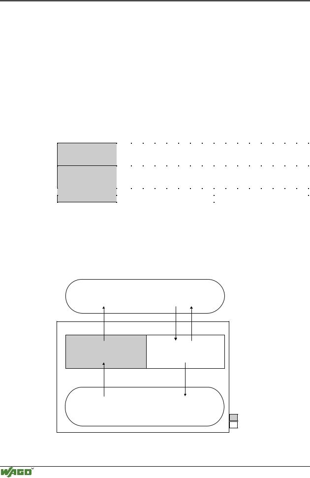
3.2.5.3Data exchange between master and I/O modules
The data exchange between the MODBUS master and the I/O modules is made via the MODBUS functions implemented in the controller by reading and writing in bits or bytes.
The controller handles four different types of process data:
•Input words
•Output words
•Input bits
•Output bits
The word for word access to the digital input and output modules is made in accordance with the following table:
Digital inputs/ outputs
Prozess data
word
Byte
16. |
15. |
14. |
13. |
12. |
11. |
10. |
9. |
8. |
7. |
6. |
5. |
4. |
3. |
2. |
1. |
|
|
|
|
|
|
|
|
|
|
|
|
|
|
|
|
Bit |
Bit |
Bit |
Bit |
Bit |
Bit |
Bit |
Bit |
Bit |
Bit |
Bit |
Bit |
Bit |
Bit |
Bit |
Bit |
15 |
14 |
13 |
12 |
11 |
10 |
9 |
8 |
7 |
6 |
5 |
4 |
3 |
2 |
1 |
0 |
|
|
|
|
|
|
|
|
|
|
|
|
|
|
|
|
High-Byte |
|
|
|
|
|
|
Low-Byte |
|
|
|
|
|
|
||
D1 |
|
|
|
|
|
|
|
D0 |
|
|
|
|
|
|
|
Table 3.10: Allocation of digital inputs/outputs to process data word acc. Intel format
Adding 0x0200 to the MODBUS address permits to read back the outputs.
The register functions addressing can be by the means of the implemented MODBUS function codes (read/write). The individual register address is referenced instead of the address of a module channel.
MODBUS master |
||
0x000 |
0x000 |
|
|
(0x200) |
|
PII |
PIO |
|
0x0FF |
0x0FF |
|
(0x2FF) |
||
|
||
Inputs |
Outputs |
|
|
I/O modules |
|
|
PII = Process Input |
|
|
Image |
|
|
PIO = Process Output |
|
|
Image |
|
Programmable Fieldbus Controller
Fig. 3-27: Data exchange between MODBUS master and I/O modules |
g012929e |
Modular I/O System
ETHERNET TCP/IP
Fieldbus controller 750-842 • 71
Data exchange
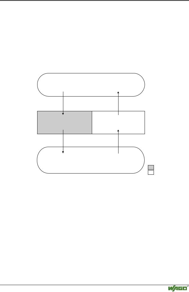
3.2.5.4Data exchange between PLC functionality (CPU) and I/O modules
Through absolute addresses, the PLC functionality (CPU) of the PFC can directly address the bus module data.
The PFC addresses the input data with absolute addresses. The data can then be processed, internally in the controller, through the IEC 61131-3 program, whereby the flags are filed in a permanent memory area. Following this, the linking results can be directly written in the output data via absolute addressing.
Inputs |
Outputs |
I/O modules |
750-4xx....6xx |
%IW0 |
%QW0 |
PII |
PIO |
%IW255 |
%QW255 |
Inputs |
Outputs |
PLC functionality (CPU)
PII = Process Input
Image
PIO = Process Output
Image
Programmable Fieldbus Controller
Fig. 3-28: Data exchange between PLC functionality (CPU) and I/O modules |
g012943e |
Modular I/O System
ETHERNET TCP/IP
72 • Fieldbus controller 750-842
Data exchange
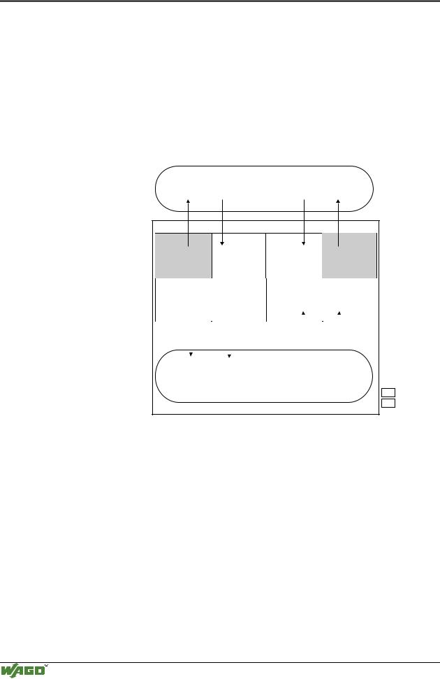
3.2.5.5Data exchange between master and PLC functionality (CPU)
The MODBUS master and the PLC functionality (CPU) of the PFC regard the data in a different manner.
Variables data created by the master reach the PFC as input variables and are further treated there.
Data created in the PFC is sent to the master through the fieldbus as output variables.
In the PFC the system can access the variable’s data as from I/O word address 256 (double word address 128, byte address 512).
MODBUS master
PII |
|
PIO |
PII |
0x000 |
0x100 |
0x000 |
0x100 |
|
(0x300) |
(0x200) |
|
Data from point of view |
|
|
|
|
|
I/O modules |
|
variables |
|
|||||||
I/O modules |
|
|
variables |
|
||||||||||||
of MODBUS master |
|
|
||||||||||||||
|
|
|
|
0x1FF |
0x0FF |
|
|
0x1FF |
|
|||||||
|
|
0x0FF |
|
|
|
|
||||||||||
|
|
|
|
|
|
(0x3FF) |
(0x2FF) |
|
|
|
|
|
||||
|
|
|
|
|
|
|
|
|
|
|
|
|
|
|
|
|
|
|
%IW0 |
|
%IW256 |
%QW0 |
|
|
%QW256 |
|
|
|
|||||
Data from point of view |
I/O modules |
|
variables |
I/O modules |
|
|
variables |
|
|
|
||||||
of PLC functionality |
|
|
|
|
|
|
||||||||||
|
|
|
|
|
|
|
|
|
|
|
|
|
|
|
||
|
|
|
|
|
|
|
|
|
|
|
|
|
|
|
|
|
|
|
%IW255 |
|
|
|
%IW511 |
%QW255 |
|
|
|
|
|
%QW511 |
|
|
|
|
|
|
|
|
|
|
|
|
|
|
||||||
|
|
|
SPS-PII |
|
|
|
SPS-PIO |
|
|
|
|
|
||||
|
|
|
|
|
|
|
|
|
|
|
|
|
|
|
|
|
|
|
|
|
|
|
|
|
|
|
|
|
|
|
|
||
|
|
|
Inputs |
|
|
|
Outputs |
|
|
|
|
|
||||
|
|
|
PLC functionality (CPU) |
|
||||||||||||
|
|
|
|
|
|
|
|
|
|
|
|
|
|
|
|
|
|
|
|
|
|
|
|
|
|
|
|
|
|
|
|
PII |
= Process Input |
|
|
|
|
|
|
|
|
|
|
|
|
|
|
|
|
Image |
|
|
|
|
|
|
|
|
|
|
|
|
|
|
|
PIO |
= Process Output |
|
|
|
|
|
|
|
|
|
|
|
|
|
|
|
|
Image |
|
|
|
Programmable Fieldbus Controller |
|
|
|
|
|
||||||||
Fig. 3-29: Data exchange between MODBUS master and PLC functionality |
g012944e |
|||||||||||||||
Data access by the MODBUS master
The data can only be accessed by the MODBUS master either word by word or bit by bit.
Addressing the data from the bus modules starts with word 0 for a word- by-word access, and also with 0 in word 0 for bit 0 for a bit-by-bit access.
Addressing the data from the variables starts with word 256 for a word-by- word access, and then, with a bit-by-bit access, addressing starts from:
4096 for bit 0 in word 256
4097 for bit 1 in word 256
...
8191 for bit 15 in word 511.
Modular I/O System
ETHERNET TCP/IP

Fieldbus controller 750-842 • 73
Data exchange
The bit number can be defined using the following formula:
BitNo = (Word * 16) + Bitno_in_Word
Data access by the PLC functionality
When accessing the same data, the PLC functionality of the PFCs uses a different type of addressing.
When declaring 16 bit variables, the PLC addressing is identical to the addressing of the MODBUS master made word-by-word.
When declaring Boolean variables (1 bit) a notation different to that of the MODBUS is used.
The bit address is composed of the elements word address and bit number in the word, separated by a dot.
Example:
Bit access MODBUS to bit number 4097 => bit addressing in the PLC <Wordno>.<Bitno> = 0.1
The PLC functionality of the PFC can also access the data byte-by-byte and double word-by-double word.
With the bytewise access, the addresses are computed according to the following formula:
High-Byte Address = Word address*2 Low-Byte Address = (Word address*2) + 1
With the access by a double word, the address is computed according to the following formula:
Double word address = High word address/2 (rounded off) or = Low word address/2
3.2.5.6Common access of MODBUS master and PLC functionality to outputs
The process illustration of outputs is described both by the MODBUS master as well as by the PLC functionality, so that the I/O module outputs can be set or reset from both sides. Design the user programs of the MODBUS master and the PLC functionality such that conflicting instructions for simultaneous setting or resetting of outputs is excluded.
Modular I/O System
ETHERNET TCP/IP