


Fieldbus coupler 750-342 • 41
LED Display
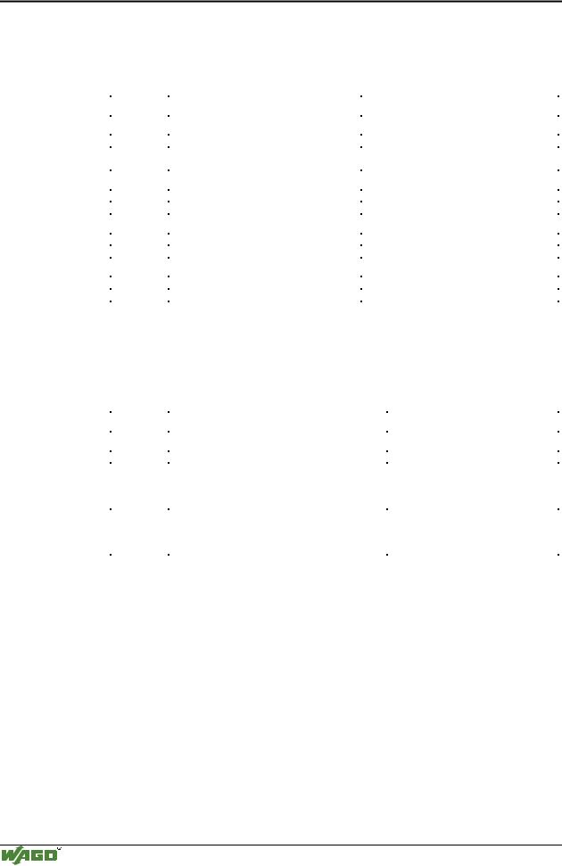
3.1.7LED Display
The coupler possesses several LED’s for displaying the coupler operating status and the complete node status.
ETHERNET |
01 |
02 |
status |
|
voltage supply |
|
|||
ON |
A |
|
|
|
|
-power jumper contacts |
|
||
|
|
|
||
|
|
C |
|
|
LINK |
B |
|
-system |
|
|
D |
|
||
TxD/RxD |
24V 0V |
|
|
|
ERROR |
|
|
|
|
I/O |
+ |
+ |
|
|
|
|
|
||
Fig. 3-15: Display elements 750-342 |
G012901e |
|||
A differentiation is made between the two groups of LEDs.
The first group = fieldbus contains the solid color LEDs having the designation ON (green), LINK (green), TxD/RxD (green) and ERROR (red) indicating the operating status of the communication via ETHERNET.
The second group = internal bus consists of the three-color I/O LED (red/green/orange). This LED is used to display the status of the internal bus and i. e. the status of the fieldbus node.
LEDs located on the right-hand side in the coupler feed section, show the status of the supply voltage.
3.1.7.1Blink code
A blink code displays detailed fault messages. A fault is cyclically displayed using up to 3 different blink sequences.
•The first blink sequence (approx. 10 Hz) indicates the fault display.
•After a pause a second blink sequence appears (approx. 1 Hz). The number of blink impulses gives the fault code.
•The third blink sequence (approx. 1 Hz) appears following a further pause. The number of blink pulses indicates the fault argument.
Modular I/O System
ETHERNET TCP/IP
42 • Fieldbus coupler 750-342
LED Display
3.1.7.2Fieldbus status
The operating status of the communication via ETHERNET is signalled by means of the top LED group (ON, LINK, TxD/RxD and ERROR).
LED |
Meaning |
Trouble shooting |
|
|
|
ON |
|
|
|
|
|
green |
Fieldbus initialization is correct |
|
OFF |
Fieldbus initialization is not correct, |
Check the supply voltage (24V and 0V), |
|
no function or self-test |
check the IP configuration |
LINK |
|
|
|
|
|
green |
Link to a physical network exists |
|
OFF |
No link to a physical network |
Check the fieldbus connection. |
TxD/RxD |
|
|
|
|
|
green |
Data exchange taking place |
|
OFF |
No data exchange |
|
ERROR |
|
|
|
|
|
red |
Error on the fieldbus |
|
OFF |
No error on the fieldbus, normal operation |
|
3.1.7.3Node status
The operating status of the communication via the internal bus is signalled via the bottom I/O LED.
LED |
Meaning |
Trouble shooting |
|
|
|
I/O |
|
|
|
|
|
Green |
Fieldbus coupler operating perfectly |
|
Red |
a) During startup of fieldbus coupler: |
|
|
Internal bus being initialized, |
|
|
Startup displayed by LED flashing fast for approx. |
|
|
1-2 seconds |
|
Red |
b) After startup of fieldbus coupler: |
|
|
Errors, which occur, are indicated by three conse- |
Evaluate the fault message (fault code and |
|
cutive flashing sequences. There is a short pause |
fault argument). |
|
between each sequential flash. |
|
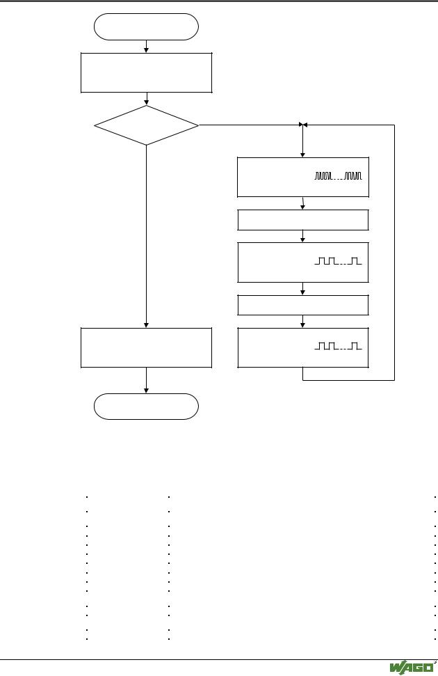
The coupler starts up after switching on the supply voltage. The "I/O" LED blinks. The "I/O" LED has a steady light following a fault free run-up.
In the case of a fault the "I/O" LED continues blinking. The fault is cyclically displayed by the blink code.
Modular I/O System
ETHERNET TCP/IP
Fieldbus coupler 750-342 • 43
LED Display
Switching on the power supply
Coupler/Controller starts up
“I/O”-LED is blinking
No
Test o.k.?
Yes
“I/O”-LED is shining
ready for operation
“I/O” LED
1st flash sequence
(Introduction of the error indication)
1st break
“I/O” LED
2nd flash sequence
Error code
(Number of flash cycles)
2nd break
“I/O” LED
3rd flash sequence
Error argument
(Number of flash cycles)
Fig. 3-16: Signalling of the LED for indication of the node status |
g012911e |
After clearing a fault, restart the coupler by cycling the power.
3.1.7.4Fault message via blink code from the I/O-LED
Fault argument |
Fault description |
|
|
Fault code 1: Hardware and Configuration fault |
|
|
|
0 |
EEPROM check sum fault / check sum fault in the parameter area of the flash memory |
1 |
Overflow of the internal buffer memory for the inline code |
2 |
Unknown data type |
3 |
Module type of the flash program memory could not be determined / is incorrect |
4 |
Fault when writing in the FLASH memory |
5 |
Fault when deleting the FLASH memory |
6 |
Changed I/O module configuration determined after AUTORESET |
Fault code 2: Fault in programmed configuration |
|
|
|
0 |
Incorrect table entry |
Fault code 3: Internal bus command fault |
|
|
|
0 |
No error argument is put out. |
Modular I/O System
ETHERNET TCP/IP
44 • Fieldbus coupler 750-342 LED Display
Fault code 4: Internal bus data fault
0 |
Data fault on internal bus or |
|
|
Internal bus interruption on coupler |
|
n* (n>0) |
Internal bus interrupted after I/O module n |
|
Fault code 5: Fault during register communication |
||
|
|
|
n* |
Internal bus fault during register communication after I/O module n |
|
Fault code 6: Fieldbus specific error |
||
|
|
|
1 |
No reply from the BootP server |
|
2 |
ETHERNET controller not recognized |
|
3 |
Invalid MACID |
|
4 |
TCP/IP initialization error |
|
Fault code 7: I/O module is not supported |
||
|
|
|
n* |
|
I/O module at position n is not supported |
Fault code 8: not used |
|
|
|
|
|
0 |
|
Fault code 8 is not used. |
Fault code 9: CPU-TRAP error |
||
|
|
|
1 |
|
Illegal Opcode |
2 |
|
Stack overflow |
3 |
|
Stack underflow |
4 |
|
NMI |
* The number of blink pulses (n) indicates the position of the I/O module. I/O modules without data are not counted (i.e. supply modules without diagnostics).
Example for a fault message
Fault: The 13th I/O module has been removed.
1.The "I/O" LED starts the fault display with the first blink sequence (approx. 10 Hz).
2.The second blink phase (approx. 1 Hz) follows the first pause. The "I/O" LED blinks four times and thus signals the fault code 4 (internal bus data fault).
3.The third blink sequence follows the second pause. The "I/O ERR" LED
blinks twelve times. The fault argument 12 means that the internal bus is interrupted after the 12th I/O module. Supply voltage status
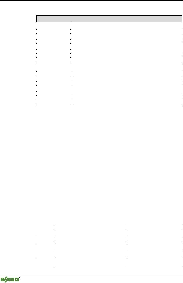
There are two green LED’s in the coupler supply section to display the supply voltage. The left LED (A) indicates the 24 V supply for the coupler. The right hand LED (C) signals the supply to the field side, i.e. the power jumper contacts.
LED |
Meaning |
Trouble shooting |
|
|
|
A |
|
|
|
|
|
green |
Operating voltage for the system exists. |
|
OFF |
No operating voltage for the system. |
Check the supply voltage (24V and 0V). |
C |
|
|
|
|
|
green |
Operating voltage for the power jumper contacts |
|
|
exists. |
|
OFF |
No operating voltage for the the power jumper con- |
Check the supply voltage (24V and 0V). |
|
tacts. |
|
Modular I/O System
ETHERNET TCP/IP