- •TABLE OF CONTENTS
- •Important comments
- •Legal principles
- •Copyright
- •Personnel qualification
- •Intended use
- •Scope
- •Symbols
- •Font conventions
- •Number notation
- •Abbreviation
- •The WAGO-I/O-SYSTEM 750
- •System Description
- •General
- •Coupler/Controller (1)
- •I/O Modules (2)
- •End Module (3)
- •Installation
- •Safty notes
- •Mechanical Installation
- •Electrical Installation
- •Wire Connection
- •Change fuse
- •Power supply
- •System supply voltage
- •Supply Voltage Field Side
- •Manufacturing Number
- •Technical Data
- •Fieldbus coupler / controller
- •Fieldbus coupler 750-342
- •Description
- •Hardware
- •View
- •Device supply
- •Fieldbus connection
- •Display elements
- •Configuration interface
- •Operating system
- •Process image
- •Example of a process input image
- •Example of a process output image
- •Process data architecture for MODBUS/TCP
- •Data exchange
- •Memory areas
- •Addressing
- •Data exchange between MODBUS master and I/O modules
- •Starting up ETHERNET TCP/IP fieldbus nodes
- •Connecting PC and fieldbus node
- •Determining IP addresses
- •Allocating the IP address to the fieldbus node
- •Testing the function of the fieldbus node
- •Reading out the information as HTML pages
- •LED Display
- •Blink code
- •Fieldbus status
- •Node status
- •Fault behavior
- •Fieldbus failure
- •Internal bus fault
- •Technical Data
- •Fieldbus controller 750-842
- •Description
- •Hardware
- •View
- •Device supply
- •Fieldbus connection
- •Display elements
- •Configuration and programming interface
- •Operating mode switch
- •Operating system
- •Start-up
- •PLC cycle
- •Process image
- •Example of a process input image
- •Example of a process output image
- •Process data architecture for MODBUS/TCP
- •Data exchange
- •Memory areas
- •Addressing
- •Data exchange between master and I/O modules
- •Data exchange between PLC functionality (CPU) and I/O modules
- •Data exchange between master and PLC functionality (CPU)
- •Common access of MODBUS master and PLC functionality to outputs
- •Address review
- •Starting up ETHERNET TCP/IP fieldbus nodes
- •Connecting PC and fieldbus node
- •Determining IP addresses
- •Allocating the IP address to the fieldbus node
- •Testing the function of the fieldbus node
- •Viewing the HTML pages
- •Programming the PFC with WAGO-I/O-PRO 32
- •LED Display
- •Blink code
- •Fieldbus status
- •Node status
- •Supply voltage status
- •Fault behavior
- •Fieldbus failure
- •Internal bus fault
- •Technical Data
- •I/O modules
- •I/O modules-Review
- •Digital Inputs
- •Digital Outputs
- •Analog Inputs
- •Analog Outputs
- •Supply and End modules
- •Terminal blocks for encoder and resolvers
- •Special terminal blocks
- •ETHERNET
- •Network architecture – Principles and Regulations
- •Transmission media
- •Network topologies
- •Coupler modules
- •Important terms
- •Network communication
- •Channel access method
- •Communication protocols
- •ETHERNET
- •IP-Protocol
- •TCP protocol
- •ICMP
- •Application protocols
- •MODBUS/TCP
- •Bootstrap Protocol (BootP)
- •HyperText Transfer Protocol (HTTP)
- •Common MODBUS functions
- •Use of the MODBUS functions
- •Description of the MODBUS functions
- •Function code FC1 (Read Coils)
- •Function code FC2 (Read Discrete Inputs)
- •Function code FC3 (Read multiple registers)
- •Function code FC4 (Read input registers)
- •Function code FC5 (Write Coil)
- •Function code FC6 (Write single register)
- •Function code FC7 (Read Exception Status)
- •Function code FC16 (Write multiple registers)
- •Function code FC11 (Get comm event counter)
- •Function code FC23 (Read/Write multiple registers)
- •Watchdog (Fieldbus failure)
- •Diagnostic function
- •Configuration function
- •Firmware information
- •General Registers
- •Special PFC Register (only for controller 750-842)
- •Application examples
- •Test of MODBUS protocol and fieldbus nodes
- •Visualization and control using SCADA software
- •Application in Explosive Environments
- •Foreword
- •Protective measures
- •Classification meeting CENELEC and IEC
- •Divisions
- •Explosion protection group
- •Unit categories
- •Temperature classes
- •Types of ignition protection
- •Classifications meeting the NEC 500
- •Divisions
- •Explosion protection groups
- •Temperature classes
- •Identification
- •For Europe
- •For America
- •Installation regulations
- •Glossary
- •Literature list
- •Index

Fieldbus coupler 750-342 • 35
Starting up ETHERNET TCP/IP fieldbus nodes
3.1.6Starting up ETHERNET TCP/IP fieldbus nodes
This chapter shows the step-by-step procedure for starting up a
WAGO ETHERNET TCP/IP fieldbus node. The following also contains a description of how to read out the coupler-internal HTML pages.
Attention
This description is given as an example and is limited to the execution of a local startup of an individual ETHERNET fieldbus node with a computer running under windows which is not connected to a network.
Direct Internet connection should only be performed by an authorized network administrator and is, therefore, not described in this manual.
The procedure contains the following steps:
1.Noting the MAC-ID and establishing the fieldbus node
2.Connecting the PC and fieldbus node
3.Determining the IP address
4.Allocation of the IP address to the fieldbus node
5.Function of the fieldbus tests
6.Reading out information as HTML pages
3.1.6.1Note the MAC-ID and establish the fieldbus node
Before establishing your fieldbus node, please note the hardware address (MAC-ID) of your ETHERNET fieldbus coupler.
This is located on the rear of the fieldbus coupler and on the self-adhesive tearoff label on the side of the fieldbus coupler.
MAC-ID of the fieldbus coupler will be in this format:
---------- ----- ----- ----- -----.
3.1.6.2Connecting PC and fieldbus node
Connect the assembled ETHERNET TCP/IP fieldbus node via a hub or directly to the PC using a 10Base-T cable.
Attention
For a direct connection, a crossover cable is required instead of a parallel cable.
Now start the PC, functioning as master and BootP server, and switch on the voltage supply on the fieldbus coupler (DC 24 V power pack). Once the operating voltage has been switched on, the initialization starts. The fieldbus coupler determines the configuration of the bus modules and creates the process image.
During the startup the ’I/O’LED (Red) flashes at high frequency.
When the ’I/O’LED and the ’ON’LED light up green, the fieldbus coupler is ready for operation.
If an error has occurred during startup, it is indicated as an error code by the ’I/O’-LED flashing (red).
Modular I/O System
ETHERNET TCP/IP

36 • Fieldbus coupler 750-342
Starting up ETHERNET TCP/IP fieldbus nodes
3.1.6.3Determining IP addresses
If your PC is already connected to an ETHERNET network, it is very easy to determine the IP address of your PC. To do this, proceed as follows:
1.Go to the Start menu on your screen, menu item Settings and click on Control Panel.
2.Double click the icon Network.  The network dialog window will open.
3.- Under Windows NT: Select the register: Protocols and mark
the entry TCP/IP protocol.
- Under Windows 9x: Select the register: Configuration and mark the entry TCP/IP network card.
Attention
If the entry is missing, please install the respective TCP/IP component and restart your PC. The Windows-NT installation CD, or the installations CD for Windows 9x is required for the installation.
4.Subsequently, click the button "Properties...".
The IP address and the subnet mask are found in the ‘IP address’ tab.If applicable, the gateway address of your PC is found in the ‘Gateway’ tab.
5.Please write down the values:
IP address PC: |
----- . ----- |
. ----- |
. ----- |
Subnet mask: |
----- . ----- |
. ----- |
. ----- |
Gateway: |
----- . ----- |
. ----- |
. ----- |
6. Now select a desired IP address for your fieldbus node.
Attention
When selecting your IP address, ensure that it is in the same local network in which your PC is located.
7. Please note the IP address you have chosen:
IP address fieldbus node: |
----- . ----- |
. ----- |
. ----- |
3.1.6.4Allocating the IP address to the fieldbus node
The following describes how to allocate the IP address for the fieldbus node using the WAGO BootP server by way of an example. You can download a free copy from WAGO over the Internet under: http://www.wago.com/wagoweb/usa/eng/support/downloads/index.htm.
Modular I/O System
ETHERNET TCP/IP

Fieldbus coupler 750-342 • 37
Starting up ETHERNET TCP/IP fieldbus nodes
Note
The IP address can be allocated under other operating systems (i.e. under Linux) as well as with any other BootP servers.
Attention
The IP address can be allocated in a direct connection via a crossover cable or via a parallel cable and a hub. An allocation over a switch is not possible.
BootP table
Note
Prerequisite for the following steps is the correct installation of the WAGO BootP server.
1.Go to the Start menu, menu item Programs / WAGO Software / WAGO BootP Server and click on WAGO BootP Server configuration.
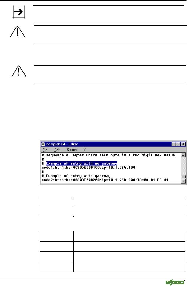
An editable table will appear: "bootptab.txt".
This table displays the data basis for the BootP server. Directly following the list of all notations used in the BootP table there are two examples for the allocation of an IP address.
"Example of entry with no gateway" and "Example of entry with gateway".
Fig. 3-11: BootP table |
p012908e |
The examples mentioned above contain the following information:
Declaration |
Meaning |
|
node1, |
Any name can be given for the node here. |
|
node2 |
||
|
||
ht=1 |
Specify the hardware type of the network here. |
|
|
The hardware type for ETHERNET is 1. |
|
|
(The numbers are described in RFC1700) |
ha=0030DE000100
ha=0030DE000200
ip= 10.1.254.100 ip= 10.1.254.200
T3=0A.01.FE.01
Specify the hardware address or the MAC-ID of the ETHERNET fieldbus coupler (hexadecimal).
Enter the IP address of the ETHERNET fieldbus coupler (decimal) here.
Specify the gateway IP address here.
Write the address in hexadecimal form.
sm=255.255.0.0 In addition enter the Subnet-mask of the subnet (decimal), where the ETHERNET fieldbus coupler belongs to.
Modular I/O System
ETHERNET TCP/IP

38 • Fieldbus coupler 750-342
Starting up ETHERNET TCP/IP fieldbus nodes
No gateway is required for the local network described in this example. Therefore, the first example: "Example of entry with no gateway" can be used.
2.Move the mouse pointer to the text line: "node1:ht=1:ha=0030DE000100:ip=10.1.254.100" and mark the 12 character hardware address which is entered after ha=...
Enter the MAC-ID of your own network coupler.
3.If you want to give your fieldbus node a name, delete the name "node1" and enter any name in its place.
4.To assign the coupler a desired IP address, mark the IP address specified in the example which is entered after ip=...
Replace it with the IP address you have selected.
5.Because the second example is not necessary at present, insert a “#” in front of the text line of the second example: "# node2:hat=1:ha=003 0DE 0002 00:ip=10.1.254.200:T3=0A.01.FE.01", so that this line will be ignored.
Note
To address more fieldbus nodes, enter a corresponding text line showing the corresponding entries for each node.
6.Save the altered settings in this text file "bootptab.txt". To do this go to the File menu, menu item Save, and close the editor.
BootP Server
7.Now open the dialog window for the WAGO BootP server by going to the Start menu on your screen surface, menu item Program /
WAGO Software / WAGO BootP Server and click on WAGO BootP
Server.
8.Click on the "Start" button in the opened dialog window.
This will activate the inquiry/response mechanism of the BootP protocol. A series of messages will be displayed in the BootP server. The error messages indicate that some services (i.e. port 67, port 68) in the operating system have not been defined.
Modular I/O System
ETHERNET TCP/IP
