


Fieldbus coupler 750-342 • 31
Data exchange
3.1.5Data exchange
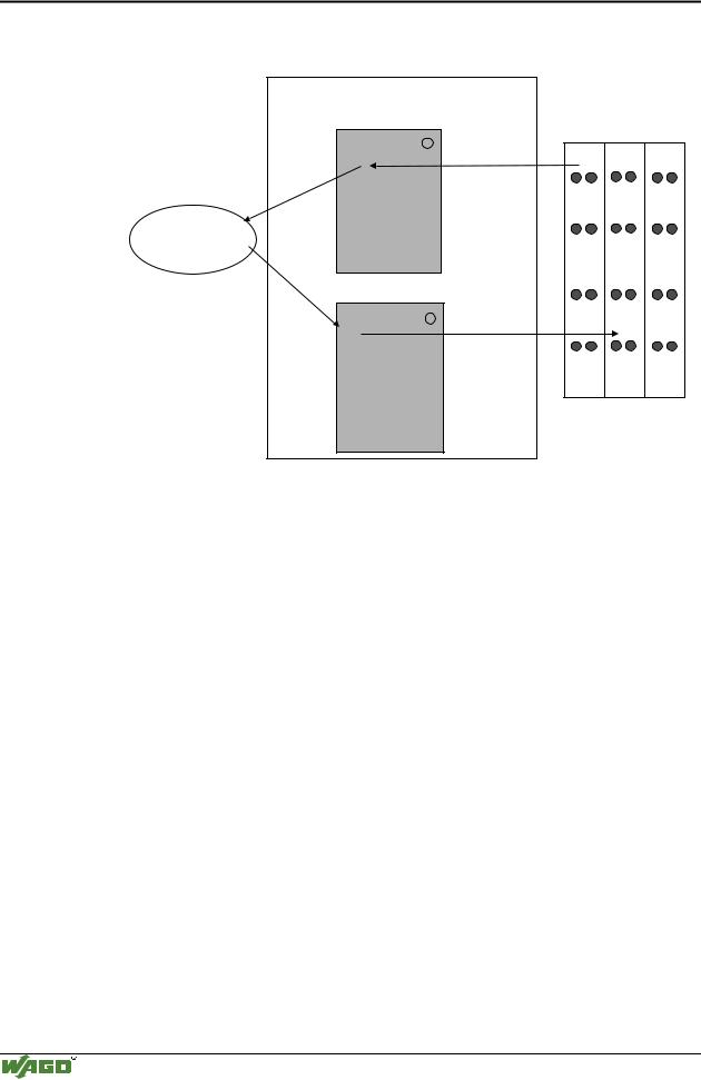
Process data exchange with the ETHERNET TCP/IP fieldbus coupler occurs via the MODBUS/TCP protocol.
MODBUS/TCP works according to the master/slave principle. The master is a superimposed control unit, i.e. a PC or a PLC device. The ETHERNET TCP/IP couplers of the WAGO-I/O-SYSTEM are slave devices.
The master makes a query for communication. Through adressing, this query can be sent to a specific node. The nodes receive the query and return a response to the master, depending on the kind of query.
A coupler can communicate with a certain number of simultaneous connections (socket connections) to other network subscribers:
•1 connection for HTTP (reading HTML pages from coupler) and
•3 connections via MODBUS/TCP (reading or writing input and output data from coupler).
The maximum number of simultaneous connections cannot be exceeded. If further connections are to be made, terminate existing connections beforehand.
For a data exchange, the ETHERNET TCP/IP fieldbus coupler is equipped with two interfaces:
•the interface to fieldbus (-master) and
•the interface to the bus modules.
Data exchange takes place between MODBUS master and the bus modules. The master accesses the bus module data via implemented MODBUS functions.
Modular I/O System
ETHERNET TCP/IP
32 • Fieldbus coupler 750-342
Data exchange
3.1.5.1Memory areas
|
fieldbus coupler |
|
|
|
memory area |
|
|
|
for input data |
I/O modules |
|
|
word 0 |
||
|
|
|
|
|
1 |
|
|
|
input |
|
|
|
modules |
|
|
fieldbus |
|
|
|
master |
word 255 |
|
|
|
memory area |
|
|
|
for output data |
|
|
|
word 0 |
|
|
|
2 |
|
|
|
output |
|
|
|
modules |
|
|
|
|
I |
O |
word 255
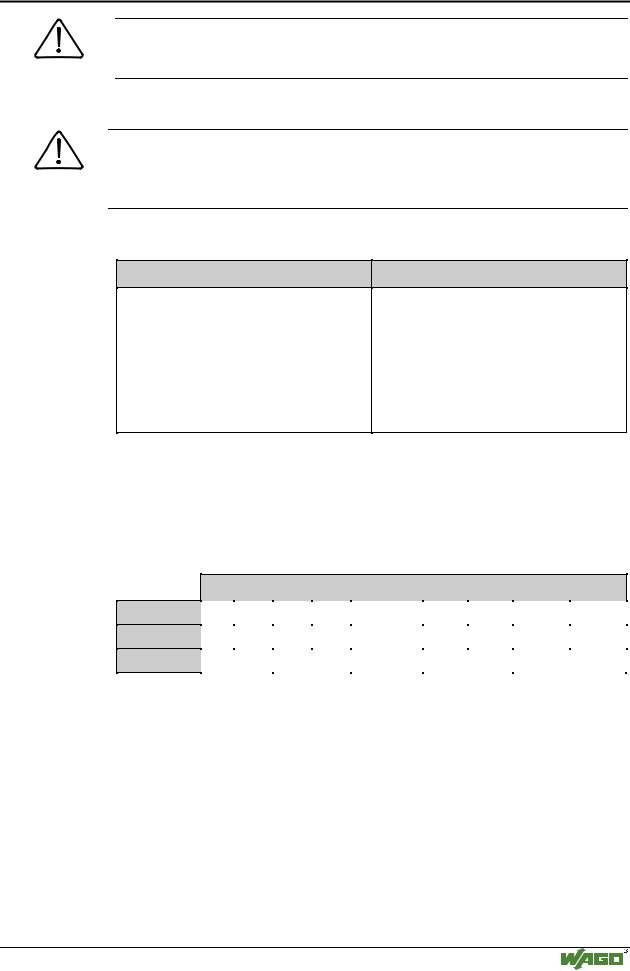
Fig. 3-9: Memory areas and data exchange for a fieldbus coupler |
g012939e |
The coupler process image contains the physical data of the bus modules in a storage area for input data and in a storage area for output data (word 0 ... 255 each).
(1)The input module data can be read from the fieldbus side.
(2)In the same manner, writing on the output modules is possible from the fieldbus side.
In addition, all output data of the ETHERNET TCP/IP coupler are mirror imaged on a storage area with the address offset 0x0200. This allows to read output values back by adding 0x0200 to the MODBUS address.
3.1.5.2Addressing
3.1.5.2.1 Addressing the I/O modules
The arrangement of the I/O modules in a node is optional.
When addressing, first of all the more complex modules (modules occupying 1 or more bytes) are taken into account in accordance with their physical order behind the fieldbus coupler. As such, they occupy the addresses starting with word 0.
Following this, the data of the other modules (modules occupying less than 1 byte) follow, grouped into bytes. In accordance with the physical byte-wise order this data is used to fill up the bytes. As soon as a full byte is occupied by the bit-oriented modules, the next byte is automatically started.
Modular I/O System
ETHERNET TCP/IP
Fieldbus coupler 750-342 • 33
Data exchange
Note
For the number of input and output bits and/or bytes of the individual activated bus modules, please refer to the pertaining descriptions of the bus modules.
Note
Once a node is modified, a new architecture of the process image can result. As such, the address of the process data will alsochange. In the event of adding modules, the process data of all previous modules has to be taken into account.
Data width • :RUG FKDQQHO
Analog input modules
Analog output modules
Input modules for thermal elements
Input modules for resistance sensors
Pulse width output modules
Interface module
Up/down counter
I/O modules for angle and path measurement
Data width = 1 Bit / channel
Digital input modules
Digital output modules
Digital output modules with diagnosis (2 Bit / channel)
Power supply modules with fuse holder / diagnosis
Solid State power relay
Relay output modules
Table 3.1: I/O module data width
3.1.5.2.2 Address range
Address range for I/O module data:
Datawidth Address
Bit
Byte
Word
0.0 |
...0.8 |
...1.0 |
...1.8 |
..... |
...254.0 |
...254.8 |
...255.0 |
...255.8 |
... |
0.15 |
1.7 |
1.15 |
|
254.7 |
254.15 |
255.7 |
255.15 |
0 |
1 |
2 |
3 |
..... |
508 |
509 |
510 |
511 |
|
|
|
|
|
|
|
|
|
0 |
|
1 |
|
..... |
254 |
|
255 |
|
|
|
|
|
|
|
|
|
|
Table 3.2: Address range for the I/O module data
The register functions are to be found as from 0x1000 and can be addressed along with the implemented MODBUS function codes (read/write).
Modular I/O System
ETHERNET TCP/IP
34 • Fieldbus coupler 750-342
Data exchange
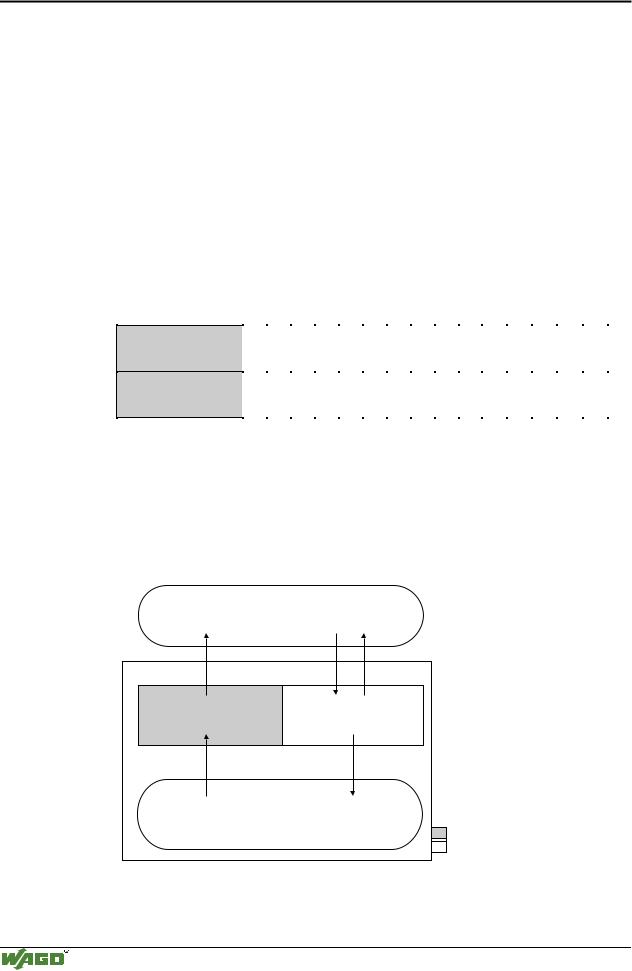
3.1.5.3Data exchange between MODBUS master and I/O modules
The data exchange between the MODBUS master and the I/O modules is made by the implemented MODBUS functions in the coupler with reading and writing in bits or bytes.
The controller handles four different types of process data:
•Input words
•Output words
•Input bits
•Output bits
The word for word access to the digital input and output modules is made in accordance with the following table:
Digital inputs/ outputs
Process data
word
16. |
15. |
14. |
13. |
12. |
11. |
10. |
9. |
8. |
7. |
6. |
5. |
4. |
3. |
2. |
1. |
|
|
|
|
|
|
|
|
|
|
|
|
|
|
|
|
Bit |
Bit |
Bit |
Bit |
Bit |
Bit |
Bit |
Bit |
Bit |
Bit |
Bit |
Bit |
Bit |
Bit |
Bit |
Bit |
15 |
14 |
13 |
12 |
11 |
10 |
9 |
8 |
7 |
6 |
5 |
4 |
3 |
2 |
1 |
0 |
|
|
|
|
|
|
|
|
|
|
|
|
|
|
|
|
Table 3.3: Allocation of digital inputs/outputs to process data word acc. Intel format
The outputs can be read back by adding 0x0200 to the MODBUS address.
The register functions made available in the coupler, can be addressed by the MODBUS master along with the implemented MODBUS function codes (read/write). To this effect, the individual register address is entered in place of the address of a module channel.
MODBUS master |
||
0x000 |
0x000 |
|
|
(0x200) |
|
PII |
PIO |
|
0x0FF |
0x0FF |
|
(0x2FF) |
||
|
||
Inputs |
Outputs |
|
|
I/O modules |
|
|
PII = Process Input |
|
|
Image |
|
|
PIO = Process Output |
|
|
Image |
|
Fieldbus Coupler
Fig. 3-10: Data exchange between the MODBUS master and I/O modules |
g012927e |
Modular I/O System
ETHERNET TCP/IP