

2 - The Visualization Editor in CoDeSys
Dialog Box for Configuring Visualization Elements (Text Category)
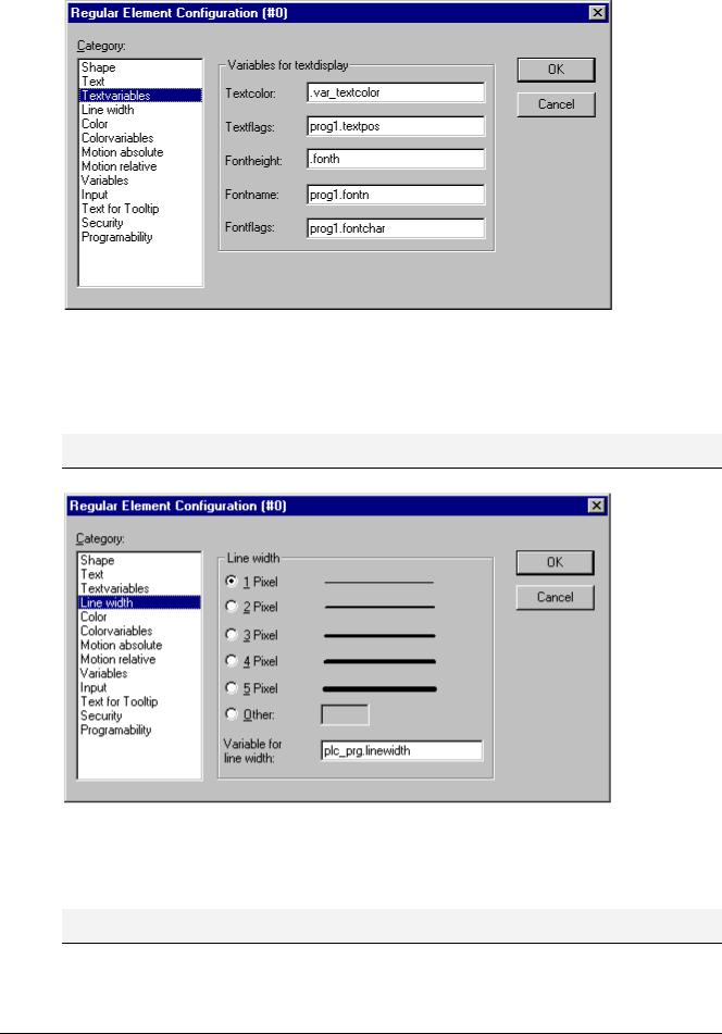
Textvariables
In category Textvariables of the dialog for configuring visualization elements you can specify a variable which should dynamically set color and font of that string which is defined in category 'Text'. At best enter the variable name with the aid of the input assistant (<F2>).
You can also use components of the structure VisualObjectType to set the text properties. For this see the description of category 'Programability'; there you will find the possible values of the particular structure components and their effect.
Note: If there are corresponding static definitions in category 'Text', these will be overwritten by the dynamic parameter values.
In case of multiple definition of an element property consider the specific order of precedence concerning according to which a value might be overwritten in online mode by another.
The parameters of the dialog:
Parameter: |
Meaning: |
Example entry of |
Example Usage of variable |
corresponding |
|
|
|
project variable: |
in program: |
component of |
|
|
|
|
|
structure |
|
|
|
|
|
VisualObjectType: |
|
|
|
|
|
|
|
Textcolor: |
Text color |
"plc_prg.var_textcolor" |
var_textcolor=16#FF00FF |
dwTextColor |
|
|
|
|
→ Farbe |
|
|
|
|
|
|
|
|
Textflags: |
Alignment |
"plc_prg.textpos" |
textpos:=2 |
dwTextFlags |
|
|
(right, left, |
|
→ Text right justified |
|
|
|
centered...) |
|
|
|
|
|
|
|
|
|
|
Fontheight: |
Font height in |
".fonth" |
fonth:=16; |
ntFontHeight |
|
|
Pixel |
|
→ Font height 16 pt |
|
|
|
|
|
|
|
|
Fontname: |
Font name |
"vis1.fontn" |
fontn:=arial; |
stFontName |
|
|
|
|
→ Arial is used |
|
|
|
|
|
|
|
|
Fontflags: |
Font display |
"plc_prg.fontchar" |
fontchar:=2 |
dwFontFlags |
|
|
(bold, |
|
→ Text will be displayed |
|
|
|
underlined, |
|
bold |
|
|
|
italic...) |
|
|
|
|
|
|
|
|
|
The CoDeSys Visualization |
2-15 |
2 - The Visualization Editor in CoDeSys
Dialog for configuring visualization elements (category Textvariables)
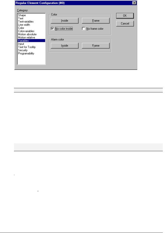
Line width
In the dialog for configuring visualization elements, you can choose the line width for an element. As predefined options you find width settings from 1 to 5 pixel, additionally an other value can be entered manually (Other:), or a project variable (Variable for line width:) can be inserted. For the latter the input assistance ((<F2>) can be used.
Note: As soon as the parameter is additionally defined dynamically, i.e. by a structure variable (see below, category 'Programmability'), the static setting will be overwritten in online mode.
Dialog Box for Configuring Visualization Elements (Line width category)
Colors
In the visualization element configuration dialog box, in the Color category you can select primary colors and alarm colors for the inside area and for the frame of your element. Chosing the options no color inside and no frame color you can create transparent elements.
Note: As soon as the parameter is additionally defined dynamically by a variable, the static setting will be overwritten in online mode.
In case of multiple definition of an element property consider the specific order of precedence concerning according to which a value might be overwritten in online mode by another.
2-16 |
The CoDeSys Visualization |
2 - The Visualization Editor in CoDeSys
Dialog Box for Configuring Visualization Elements (Color Category)
If you now enter a Boolean variable in the Variables category in the Change Color field, then the element will be displayed in the Color set, as long as the variable is FALSE. If the variable is TRUE, then the element will be displayed in its Alarm Color.
Note: The change color function only becomes active, if the PLC is in Online Mode!
If you want to change the color of the frame, then press the Frame button, instead of the Inside button. In either case, the dialog box will open for selection of the color.
Here can to choose the desired hue from the primary colors and the user-defined colors. By pressing the Define Colors you can change the user-defined colors.
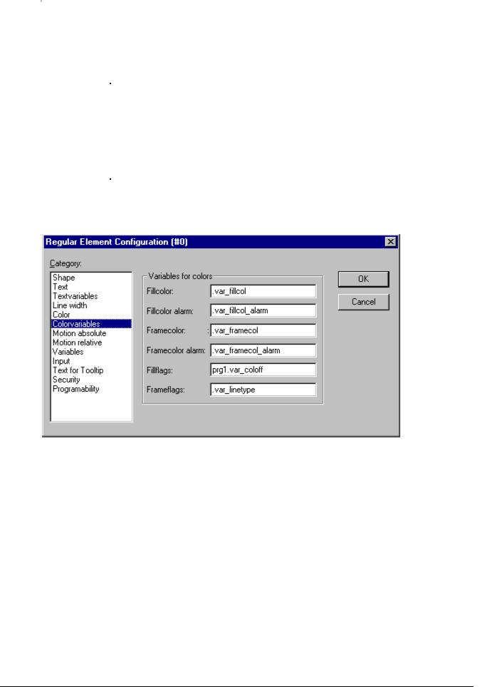
Color Variables
Here you can enter project variables (e.g. PLC_PRG.color_inside), which should determine the particular property in online mode: These property definitions also or additionally can be programmed with the aid of components of the structure VisualObjectType. Therefore see the description on the "Programability" of a visualization element. There you will find a list of the possible values and their effects.
Note: The variables, entered in the Color Variables dialog, in online mode will overwrite the static values given in the 'Color' category as well as corresponding values given by a structure variable.
In case of multiple definition of an element property consider the specific order of precedence concerning according to which a value might be overwritten in online mode by another.
The parameters of the dialog::
Parameter: |
Description: |
Example of an entry: |
Example for using the |
corresponding |
|
|
|
|
variable in the program: |
component of |
|
|
|
|
|
structure |
|
|
|
|
|
VisualObjectType: |
|
|
|
|
|
|
|
Fillcolor: |
fill color |
"plc_prg.var_fillcol" |
var_var_fillcol:=16#FF00FF |
dwFillColor |
|
|
|
|
→ fill color pink |
|
|
|
|
|
|
|
|
Fillcolor |
fill color if the |
"plc_prg.var_fillcol_ |
var_fillcol_a:=16#FF00FF |
dwFillColorAlarm |
|
alarm: |
'Change color' |
a" |
→ alarm fill color pink |
|
|
|
variable is |
|
|
|
|
|
TRUE |
|
|
|
|
|
|
|
|
|
The CoDeSys Visualization |
2-17 |
2 - The Visualization Editor in CoDeSys
Framecolor: |
frame color |
"plc_prg.var_framec |
var_framecol::=16#FF00FF |
dwFrameColor |
|
|
|
ol" |
→ frame color pink |
|
|
|
|
|
|
|
|
Framecolor |
frame color if |
"plc_prg.var_framec |
var_framecol:=16#FF00FF |
dwFrameColorAlar |
|
alarm: |
the 'Change |
ol" |
→ alarm frame color farbe |
m |
|
|
color' variable |
|
pink |
|
|
|
is TRUE |
|
|
|
|
|
|
|
|
|
|
Fillflags: |
The current |
"plc_prg.var_col_off |
var_col_off:=1 |
dwFillFlags |
|
|
inside color |
" |
→ the color definition for the |
|
|
|
configuration |
|
fill color will not be regarded, |
|
|
|
can be |
|
that for the frame remains |
|
|
|
activated |
|
valid |
|
|
|
(FALSE) resp. |
|
|
|
|
|
deactivated |
|
|
|
|
|
(TRUE) |
|
|
|
|
|
|
|
|
|
|
Frameflags: |
Display of the |
"plc_prg.var_linetyp |
var_linetype:=2; |
dwFrameFlags |
|
|
frame (solid, |
e" |
→ frame will be displayed |
|
|
|
dotted etc.) |
|
as dotted line |
|
|
|
|
|
|
|
Dialog Box for Configuring Visualization Elements (Category Colorvariables)
Motion absolute
In the visualization element configuration dialog box, in the Motion absolute category, X- or Y-Offset fields variables can be entered. These variables can shift the element in the X or the Y direction, depending on the respective variable value. A variable in the Scale field will change the size of the element linear to its current value. This value, which is used as scaling factor, will be divided by 1000 implicitely, so that it is not necessary to use REAL-variables in order to get a reduction of the element. The scaling always will refer to the balance point.
A variable in the Angle field causes the element to turn on its turning point, depending on the value of the variable. (Positive Value = Mathematic Positive = Clockwise). The value is evaluated in degrees. With polygons, every point rotates; in other words, the polygon turns. With all other elements, the element rotates, in such a way, that the upper edge always remains on top.
The turning point appears after a single click on the element, and is displayed as a small black circle with a white cross ( ). You can drag the turning point with a pressed left mouse button.
Note: |
In online |
mode the variables which are set in the 'Motion absolute' dialog will override the values of |
|
structure |
components which additionally might be used to define the same property |
|
('Programability'). |
|
2-18 |
The CoDeSys Visualization |