


3 - We Write a Little Program
3 We Write a Little Program
3.1Controlling a Traffic Signal Unit...
Let us now start to write a small example program. It is for a simple traffic signal unit which is supposed to control two traffic signals at an intersection. The red/green phases of both traffic signals alternate and, in order to avoid accidents, we will insert yellow or yellow/red transitional phases. The latter will be longer than the former.
In this example you will see how time dependent programs can be shown with the language resources of the IEC1131-3 standard, how one can edit the different languages of the standard with the help of CoDeSys, and how one can easily connect them while becoming familiar with the simulation of
CoDeSys.
Create POU
Starting always is easy: Start CoDeSys and choose 'File' 'New'.
In the dialog box which appears, the first POU has already been given the default name PLC_PRG. Keep this name, and the type of POU should definitely be a program. Each project needs a program with this name. In this case we choose as the language of this POU the Continuous Function Chart Editor (CFC)
Now create three more objects with the command 'Project' 'Object Add' with the menu bar or with the context menu (press right mouse button in the Object Organizer). A program in the language Sequential Function Chart (SFC) named SEQUENCE, a function block in the language Function Block Diagram (FBD) named TRAFFICSIGNAL, along with a POU WAIT, also of the type function block, which we want to program as an Instruction List (IL).
What does TRAFFICSIGNAL do?
In the POU TRAFFICSIGNAL we will assign the individual trafficsignal phases to the lights, i.e. we will make sure that the red light is lit red in the red phase and in the yellow/red phase, the yellow light in the yellow and yellow/red phases, etc.
What does WAIT do?
In WAIT we will program a simple timer which as input will receive the length of the phase in milliseconds, and as output will produce TRUE as soon as the time period is finished.
What does SEQUENCE do?
In SEQUENCE all is combined so that the right light lights up at the right time for the desired time period.
What does PLC_PRG do?
In PLC_PRG the input start signal is connected to the traffic lights' sequence and the "color instructions" for each lamp are provided as outputs.
TRAFFICSIGNAL simulation
Now test your program in simulation mode. Compile ('Project' 'Build') and load ('Online' 'Login') it. Start the program by 'Online' 'Start', then set variable ON to TRUE, e.g. by a double-click on the entry "ON" in the input box of the CFC editor. This will mark the variable as prepared to be set to <TRUE>. Then press <Strg><F7> or command 'Online' 'Write values', to set the value. Now variable START in ABLAUF (which we had set to TRUE manually in the first extension level of the program) gets this value by variable ON, which is used in PLC_PRG. This will make run the traffic light cycles. PLC_PRG has changed to a monitoring window. Click twice on the plus sign in the declaration editor, the variable display drops down, and you can see the values of the individual variables.
CoDeSys V2.3 |
3-1 |

Controlling a Traffic Signal Unit...
"TRAFFICSIGNAL" declaration
Let us now turn to the POU TRAFFICSIGNAL. In the declaration editor you declare as input variable (between the keywords VAR_INPUT and END_VAR) a variable named STATUS of the type INT. STATUS will have four possible conditions, that is one for the TRAFFICSIGNAL phases green, yellow, yellow/red andred.
Correspondingly our TRAFFICSIGNAL has three outputs, that is RED, YELLOW and GREEN. You should declare these three variables. Then the declaration part of our function block TRAFFICSIGNAL will look like this:
Function block TRAFFICSIGNAL, declaration part
"TRAFFICSIGNAL" body
Now we determine the values of the output variables depending on the input STATUS of the POU. To do this go into the body of the POU. Click on the field to the left beside the first network (the gray field with the number 0001). You have now selected the first network. Choose the menu item 'Insert' 'Box'.
In the first network a box is inserted with the operator AND and two inputs:
Click on the text AND, so that it appears selected and change the text into EQ. Select then for each of the two inputs the three question marks and overwrite them with "STATUS" respectively "1".
Click now on a place behind the EQ Box. Now the output of the EQ operation is selected. Choose 'Insert' 'Assign'. Change the three question marks ??? to GREEN. You now have created a network with the following structure:
STATUS is compared with 1, the result is assigned to GREEN. This network thus switches to GREEN if the preset state value is 1.
3-2 |
CoDeSys V2.3 |

3 - We Write a Little Program
For the other TRAFFICSIGNAL colors we need two more networks. To create the first one execute command 'Insert' 'Network (after)' and insert an EQ-Box like described above. Then select the output pin of this box and use again command 'Insert' 'Box'. In the new box replace "AND" by "OR". Now select the first output pin of the OR-box and use command 'Insert' 'Assign' to assign it to "GELB". Select the second input of the OR-box by a mouse-click on the horizontal line next to the three question marks, so that it appears marked by a dotted rectangle. Now use 'Insert' 'Box' to add a further EQ-box like described above. Finally the network should look like shown in the following:
Function block TRAFFICSIGNAL, instruction part
In order to insert an operator in front of another operator, you must select the place where the input to which you want to attach the operator feeds into the box.
Then use the command 'Insert' 'Box'. Otherwise you can set up these networks in the same way as the first network.
Now our first POU has been finished. TRAFFICSIGNAL, according to the input of the value STATUS, controls whichever light color we wish.
Connecting the standard.lib
For the timer in the POU WAIT we need a POU from the standard library. Therefore, open the library manager with 'Window' 'Library Manager. Choose 'Insert' 'Additional library'. The dialog box appears for opening files. From the list of the libraries choose standard.lib.
CoDeSys V2.3 |
3-3 |
Controlling a Traffic Signal Unit...
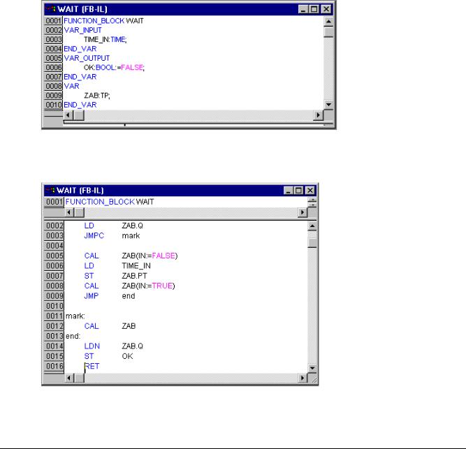
"WAIT" declaration
Now let us turn to the POU WAIT. This POU is supposed to become a timer with which we can determine the length of the time period of each TRAFFICSIGNAL phase. Our POU receives as input variable a variable TIME of the type TIME, and as output it produces a Boolean value which we want to call OK and which should be TRUE when the desired time period is finished. We set this value with FALSE by inserting at the end of the declaration (before the semicolon, however) " := FALSE ".
For our purposes we need the POU TP, a clock generator. This has two inputs (IN, PT) and two outputs (Q, ET). TP does the following:
As long as IN is FALSE, ET is 0 and Q is FALSE. As soon as IN provides the value TRUE, the time is calculated at the output ET in milliseconds. When ET reaches the value PT, then ET is no longer counted. Meanwhile Q produces TRUE as long as ET is smaller than PT. As soon as the value PT has been reached, then Q produces FALSE again. See the chapter on the standard library for short descriptions of all POUs.
In order to use the POU TP in the POU WAIT we must create a local instance from TP. For this we declare a local variable ZAB (for elapsed time) of the type TP (between the keywords VAR, END_VAR).
The declaration part of WAIT thus looks like this:
Function Block WAIT, Declaration Part
"WAIT" body
In order to create the desired timer, the body of the POU must be programmed as follows:
Function Block WAIT, Instruction Part
3-4 |
CoDeSys V2.3 |
3 - We Write a Little Program
At first it is checked whether Q has already been set at TRUE (as though the counting had already been executed), in this case we change nothing with the occupation of ZAB, but we call the function block ZAB without input (in order to check whether the time period is already over).
Otherwise we set the variable IN in ZAB at FALSE, and therefore at the same time ET at 0 and Q at FALSE. In this way all variables are set at the desired initial condition. Now we assign the necessary time from the variable TIME into the variable PT, and call ZAB with IN:=TRUE. In the function block ZAB the variable ET is now calculated until it reaches the value TIME, then Q is set at FALSE.
The negated value of Q is saved in OK after each execution of WAIT. As soon as Q is FALSE, then OK produces TRUE.
The timer is finished at this point. Now it is time to combine our two function blocks WAIT and SEQUENCE in the main program PLC_PRG.
"SEQUENCE" first expansion level
First we declare the variables we need. They are: an input variable START of the type BOOL, two output variables TRAFFICSIGNAL1 and TRAFFICSIGNAL2 of the type INT and one of the type WAIT (DELAY as delay). The program SEQUENCE now looks like shown here:
Program SEQUENCE, First Expansion Level, Declaration Part
Create a SFC diagram
The beginning diagram of a POU in SFC always consists of an action "Init" of a following transition "Trans0" and a jump back to Init. We have to expand that.
Before we program the individual action and transitions let us first determine the structure of the diagrams. We need one step for each TRAFFICSIGNAL phase. Insert it by marking Trans0 and choosing 'Insert' 'Step transition (after)'. Repeat this procedure three more times.
If you click directly on the name of a transition or a step, then this is marked and you can change it. Name the first transition after Init "START", and all other transitions "DELAY.OK".
The first transition switches through when START is TRUE and all others switch through when DELAY in OK produces TRUE, i.e. when the set time period is finished.
CoDeSys V2.3 |
3-5 |

Controlling a Traffic Signal Unit...
The steps (from top to bottom) receive the names Switch1, Green2, Switch2, Green1, whereby Init of course keeps its Name. "Switch" should include a yellow phase, at Green1 TRAFFICSIGNAL1 will be green, at Green2 TRAFFICSIGNAL2 will be green. Finally change the return address of Init after Switch1. If you have done everything right, then the diagram should look like in the following image:
Program SEQUENCE, First Expansion Level, Instruction Part
Now we have to finish the programming of the individual steps. If you double-clickon the field of a step, then you get a dialog for opening a new action. In our case we will use IL (Instruction List).
Actions and transition conditions
In the action of the step Init the variables are initialized, the STATUS of TRAFFICSIGNAL1 should be 1 (green). The state of TRAFFICSIGNAL2 should be 3 (red). The action Init then looks like in the following image:
Action Init
3-6 |
CoDeSys V2.3 |

3 - We Write a Little Program
Switch1 changes the sate of TRAFFICSIGNAL1 to 2 (yellow), and that of TRAFFICSIGNAL2 to 4 (yellow-red). In addition, a time delay of 2000 milliseconds is set. The action is now as follows:
Action Switch1
With Green2 TRAFFICSIGNAL1 is red (STATUS:=3), TRAFFICSIGNAL2 green (STATUS:=1), and the delay time is 5000 milliseconds.
Action Green2
At Switch2 the STATUS of TRAFFICSIGNAL1 changes to 4 (yellow-red), that of TRAFFICSIGNAL2 to 2 (yellow). A time delay of 2000 milliseconds is now set.
Action Switch2
With Green1 TRAFFICSIGNAL1 is green (STATUS:=1), TRAFFICSIGNAL2 is red (STATUS:=3), and the time delay is set to5000 milliseconds.
Action Green1
The first expansion phase of our program is completed. Now you can test the POU ABLAUF in simulation mode. Compile the project: 'Project' 'Build'. In the message window you should get "0 Errors, 0 Warnings". Now check if option 'Online' 'Simulation' is activated and use command 'Online' 'Login' to get into simulation mode. Start program with 'Online' 'Start'. Open POU ABLAUF by a double-click on entry "ABLAUF" in the Object Organizer. The program is started now, but to get it run, variable START must be TRUE. Later this will be set by PLC_PRG but at the moment we have to set it manually within the POU. To do that, perform a double-click on the line in the declaration part, where START is defined (START=FALSE). This will set the option "<:=TRUE>" behind the variable in turquoise color. Now select command 'Online' 'Write values' to set this value. Thereupon START will be displayed in blue color in the sequence diagram and the processing of the steps will be indicated by a blue mark of the currently active step.
CoDeSys V2.3 |
3-7 |

Controlling a Traffic Signal Unit...
When you have finished this intermediate test use command 'Online' 'Logout' to leave the simulation mode and to continue programming.
"SEQUENCE" second expansion level
In order to ensure that our diagram has at least one alternative branch, and so that we can turn off our traffic light unit at night, we now include in our program a counter which, after a certain number of TRAFFICSIGNAL cycles, turns the unit off.
At first we need a new variable COUNTER of the type INT. Declare this as usual in the declaration part of SEQUENCE, and initialize it in Init with 0.
Action Init, Second Version
Now select the transition after Switch1 and insert a step and then a transition. Select the resulting transition and insert an alternative branch to its left. After the left transition insert a step and a transition. After the resulting new transition insert a jump after Switch1.
Name the new parts as follows: the upper of the two new steps should be called "Count" and the lower "Off". The transitions are called (from top to bottom and from left to right) EXIT, TRUE and DELAY.OK. The new part should look like the part marked with the black border in the following image:
Program SEQUENCE, Second Expansion Level, Instruction Part
3-8 |
CoDeSys V2.3 |

3 - We Write a Little Program
Now two new actions and a new transition condition are to be implemented. At the step Count the variable COUNTER is increased by one:
Action Count
The EXIT transition checks whether the counter is greater than a certain value, for example 7:
Transition EXIT
At Off the state of both lights is set at 5(OFF), (or each other number not equal 1,2,3 or 4) the COUNTER is reset to 0, and a time delay of 10 seconds is set:
Action Off
The result
In our hypothetical situation, night falls after seven TRAFFICSIGNAL cycles, for ten seconds the TRAFFICSIGNAL turns itself off, then we have daylight again, the traffic light unit turns itself on again, and the whole process starts again from the beginning. If you like, do another test of the current version of your program in simulation mode before we go on to create the POU PLC_PRG.
PLC_PRG
We have defined and correlated the time sequencing of the phases for both sets of traffic lights in the block SEQUENCE. Since, however, we see the traffic lights system as a module of a bus system, e.g. CAN bus, we have to make input and output variables available in the block PLC_PRG. We want to start-up the traffic lights system over an ON switch and we want to send each of the six lamps (each traffic light red, green, yellow) the corresponding "signal command" for each step of the SEQUENCE. We are now declaring appropriate Boolean variables for these six outputs and one input, before we create the programme in the editor, and are allocating them, at the same time, to the corresponding IEC addresses.
The next step is declare the variables Light1 and Light2 of the type Phases in the declaration editor.
Declaration LIGHT1 and LIGHT2
CoDeSys V2.3 |
3-9 |

Controlling a Traffic Signal Unit...
These deliver the Boolean value of each of the six lights to the above mentioned six outputs for each step of the block SEQUENCE. We are not, however, declaring the output variables which are foreseen within the PLC_PRG block but under Resources for Global Variables instead. The Boolean input variable IN, which is used to set the variable START in the block SEQUENCE to TRUE, can be set in the same way. ON is also allocated to an IEC address.
Select the tab Resources and open the list Global Variables. Make the declaration as follows:
Declaration of the Input-/Output Variables for a CAN-Configuration
The name of the variable (e.g. IN) is followed, after AT, by a percent sign which begins the IEC address. I stands for input, Q for output, B (used in this example) stands for byte and the individual bits of the module are addressed using 0.0 (0.1, 0.2, etc.). We will not do the needed controller configuration here in this example, because it depends on which target package you have available on your computer. Please see PLC configuration for further information.
We now want to finish off the block PLC_PRG.
For this we go into the editor window. We have selected the Continuous Function Chart editor and we consequently obtain, under the menu bar, a CFC symbol bar with all of the available elements (see The Continuous Function Chart Editor).
Click on the right mouse key in the editor window and select the element Box. Click on the text AND and write "SEQUENCE" instead. This brings up the block SEQUENCE with all of the already defined input and output variables. Insert two further block elements which you name PHASES. Phases is a function block and this causes you to obtain three red question marks over the block which you replace with the already locally declared variables LIGHT1 and LIGHT2. Now set an element of the type Input, which award the title ON and six elements of the type Output which you award variable names to, as described, namely L1_green, L1_yellow, L1_red, L2_green, L2_yellow, L2_red.
All of the elements of the programme are now in place and you can connect the inputs and outputs, by clicking on the short line at the input/output of an element and dragging this with a constantly depressed mouse key to the input/output of the desired element.
Your program should finally look like shown in the following:
3-10 |
CoDeSys V2.3 |