
- •1 A Brief Introduction to CoDeSys
- •1.1 What is CoDeSys
- •1.2 Overview of CoDeSys Functions...
- •1.3 Overview on the user documentation for CoDeSys
- •2 What is What in CoDeSys
- •2.1 Project Components...
- •2.2 Languages...
- •2.2.1 Instruction List (IL)...
- •2.2.2 Structured Text (ST)...
- •2.2.3 Sequential Function Chart (SFC)...
- •2.2.4 Function Block Diagram (FBD)...
- •2.2.5 The Continuous Function Chart Editor (CFC)...
- •2.2.6 Ladder Diagram (LD)...
- •2.3 Debugging, Online Functions...
- •2.4 The Standard...
- •3 We Write a Little Program
- •3.1 Controlling a Traffic Signal Unit...
- •3.2 Visualizing a Traffic Signal Unit...
- •4 The Individual Components
- •4.1 The Main Window...
- •4.3 Managing Projects...
- •4.4 Managing Objects in a Project...
- •4.5 General Editing Functions...
- •4.8 Help when you need it...
- •5 Editors in CoDeSys
- •5.1 This is for all Editors...
- •5.2 Declaration Editor...
- •5.2.1 Working in the Declaration Editor
- •5.2.3 Pragma instructions in the Declaration Editor
- •5.3 The Text Editors...
- •5.3.1 Working in text editors
- •5.3.2 The Instruction List Editor...
- •5.3.3 The Editor for Structured Text...
- •5.4 The Graphic Editors...
- •5.4.1 Working in graphic editors
- •5.4.2 The Function Block Diagram Editor...
- •5.4.3 The Ladder Editor...
- •5.4.4 The Sequential Function Chart Editor...
- •5.4.5 The Continuous Function Chart Editor (CFC)...
- •6 The Resources
- •6.1 Overview of the Resources
- •6.2 Global Variables, Variable Configuration, Document Frame
- •6.2.1 Global Variables...
- •6.2.2 Variable Configuration...
- •6.2.3 Document Frame...
- •6.3 Alarm Configuration
- •6.3.1 Overview
- •6.3.2 General information on alarms, Terms
- •6.3.3 Alarm classes
- •6.3.4 Alarm groups
- •6.3.5 Alarm saving
- •6.3.6 'Extras' Menu: Settings
- •6.4 Library Manager...
- •6.6 PLC Configuration...
- •6.6.1 Overview
- •6.6.2 Working in the PLC Configuration...
- •6.6.3 General Settings in the PLC Configuration
- •6.6.4 Custom specific parameter dialog
- •6.6.5 Configuration of an I/O Module...
- •6.6.6 Configuration of a Channel
- •6.6.7 Configuration of Profibus Modules...
- •6.6.8 Configuration of CAN modules...
- •6.6.9 Configuration of a CanDevice (CANopen Slave)
- •6.6.10 PLC Configuration in Online Mode
- •6.6.11 Hardware scan/State/Diagnosis information from the PLC
- •6.7 Task Configuration...
- •6.7.1 Working in the Task Configuration
- •6.7.2 System Events
- •6.7.3 Taskconfiguration in Online Mode
- •6.8 Watch and Receipt Manager...
- •6.8.1 Overview
- •6.8.2 Watch and Receipt Manager in the Offline Mode
- •6.8.3 Watch and Receipt Manager in the Online Mode
- •6.9 The Sampling Trace
- •6.9.1 Overview and Configuration
- •6.9.2 Display of the Sampling Trace
- •6.9.3 'Extras' 'Save Trace'
- •6.9.4 'Extras' 'External Trace Configurations'
- •6.10 Workspace
- •6.11 Parameter Manager ..
- •6.11.1 Overview, Activating
- •6.11.2 The Parameter Manager Editor, Overview
- •6.11.3 Parameter List Types and Attributes
- •6.11.4 Managing parameter lists
- •6.11.5 Editing parameter lists
- •6.11.6 Parameter Manager in Online Mode
- •6.11.7 Export / Import of parameter lists
- •6.12 Target Settings
- •6.13 The PLC-Browser
- •6.14 Tools
- •6.14.1 Properties of available Tool Shortcuts (Object Properties)
- •6.14.2 Managing Tool Shortcuts
- •6.14.3 Frequently asked questions on Tools
- •7.1 What is ENI
- •7.2 Preconditions for Working with an ENI project data base
- •7.3 Working with the ENI project data base in CoDeSys
- •7.4 Object categories concerning the project data base
- •8 DDE Interface
- •8.1 DDE interface of the CoDeSys programming system...
- •8.2 DDE communcation with the GatewayDDE Server...
- •9 The License Management in CoDeSys
- •9.1 The License Manager
- •9.1.1 Creating a licensed library in CoDeSys
- •10 APPENDIX
- •Appendix A: IEC Operators and additional norm extending functions
- •Arithmetic Operators...
- •Bitstring Operators...
- •Selection Operators
- •Comparison Operators...
- •Address Operators...
- •Calling Operators...
- •Type Conversions...
- •Numeric Operators...
- •Appendix B: Operands in CoDeSys
- •Constants
- •Variables
- •Addresses
- •Functions
- •Appendix C: Data types in CoDeSys
- •Standard data types
- •Defined data types
- •Appendix D: The CoDeSys Libaries
- •The Standard.lib library
- •String functions...
- •Bistable Function Blocks...
- •Trigger...
- •Counter...
- •Timer...
- •The Util.lib library
- •BCD Conversion
- •Bit-/Byte Functions
- •Mathematic Auxiliary Functions
- •Controllers
- •Signal Generators...
- •Function Manipulators...
- •Analog Value Processing...
- •The AnalyzationNew.lib library
- •The CoDeSys System Libraries
- •Appendix E: Operators and Library Modules Overview
- •Appendix F: Command Line-/Command File
- •Command Line Commands
- •Command File (cmdfile) Commands
- •Appendix G: Siemens Import
- •Import from a SEQ Symbol File
- •Import from a S5 Project File
- •Converting S5 to IEC 61131-3
- •Appendix H: Target Settings in Detail
- •Settings in Category Target Platform
- •Appendix I: Use of Keyboard
- •Appendix J: Compiler Errors and Warnings
- •Warnings
- •Errors

Appendix D: - The CoDeSys Libaries
Because of the additional integral part, an overflow can come about by incorrect parameterization of the controller, if the integral of the error ∆ becomes too great. Therefore for the sake of safety a BOOLean output called OVERFLOW is present, which in this case would have the value TRUE. At the same time, the controller is suspended and will only be activated again by re-initialization.
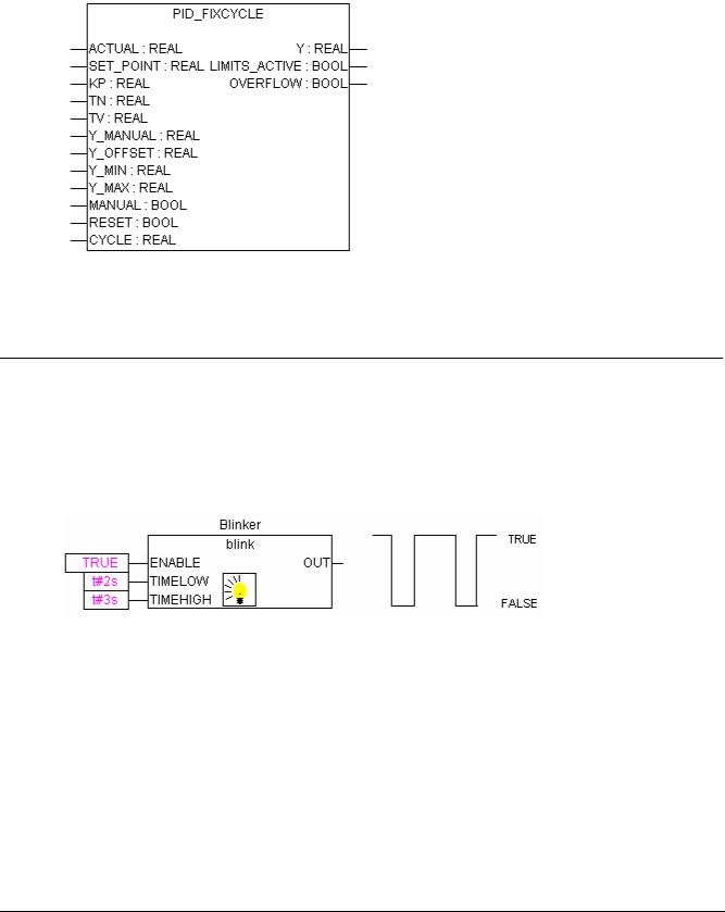
PID_FIXCYCLE
The PID_FIXCYCLE controller function block:
This function block functionally corresponds to the PID controller with the exception that the cycle time is not measured automatically by an internal function but is set by input CYCLE (in seconds).
10.17.5 Signal Generators...
BLINK
The function block BLINK generates a pulsating signal. The input consists of ENABLE of the type BOOL, as well as TIMELOW and TIMEHIGH of the type TIME. The output OUT is of the type BOOL.
If ENABLE is set to TRUE, BLINK begins, to set the output for the time period TIMEHIGH to TRUE, and then afterwards to set it for the time period TIMELOW to FALSE.
Example in CFC:
GEN
The function generator generates typical periodic functions:
The inputs are a composition consisting of MODE from the pre-defined counting type GEN_MODE, BASE of the type BOOL, PERIOD of the type TIME, of two INT values CYCLES and AMPLITUDE and of the BOOLean RESET input.
The MODE describes the function which should be generated, whereby the enumeration values TRIANGLE and TRIANGLE_POS deliver two triangular functions, SAWTOOTH_RISE an ascending, SAWTOOTH_FALL a descending sawtooth, RECTANGLE a rectangular signal and SINE and COSINE the sine and cosine:
10-54 |
CoDeSys V2.3 |

Appendix D: - The CoDeSys Libaries
TRIANGLE: |
TRIANGLE_POS: |
SAWTOOTH_RISE: SAWTOOTH_FALL:
RECTANGLE: |
SINUS: |
COSINUS:
BASE defines whether the cycle period is really related to a defined time (BASE=TRUE) or whether it is related to a particular number of cycles, which means the number of calls of function block (BASE=FALSE).
PERIOD or CYCLES defines the corresponding cycle period.
AMPLITUDE defines, in a trivial way, the amplitude of the function to be generated. The function generator is again set to 0 as soon as RESET=TRUE.
Example in FBD:
CoDeSys V2.3 |
10-55 |

Appendix D: - The CoDeSys Libaries
10.17.6 Function Manipulators...
CHARCURVE
This function block serves to represent values, piece by piece, on a linear function:
IN of the type INT is fed with the value to be manipulated. The BYTE N designates the number of points which defines the presentation function. This characteristic line is then generated in an ARRAY P[0..10] with P of the type POINT which is a structure based on two INT values (X and Y).
The output consists of OUT of the type INT, the manipulated value and BYTE ERR, which will indicate an error if necessary.
The points P[0]..P[N-1] in the ARRAY must be sorted according to their X values, otherwise ERR receives the value 1. If the input IN is not between P[0].X and P[N-1].X, ERR=2 and OUT contains the corresponding limiting value P[0]. Y or P[N-1].Y.
If N lies outside of the allowed values which are between 2 and 11, then ERR=4.
Example in ST:
First of all ARRAY P must be defined in the header:
VAR
...
CHARACTERISTIC_LINE:CHARCURVE;
KL:ARRAY[0..10] OF POINT:=(X:=0,Y:=0),(X:=250,Y:=50), (X:=500,Y:=150),(X:=750,Y:=400),7((X:=1000,Y:=1000)); COUNTER:INT;
...
END_VAR
Then we supply CHARCURVE with for example a constantly increasing value:
COUNTER:=COUNTER+10;
CHARACTERISTIC_LINE(IN:=COUNTER,N:=5,P:=KL);
The subsequent tracing illustrates the effect:
RAMP_INT
RAMP_INT serves to limit the ascendance or descendance of the function being fed:
The input consists on the one hand out of three INT values: IN, the function input, and ASCEND and DESCEND, the maximum increase or decrease for a given time interval, which is defined by TIMEBASE of the type TIME. Setting RESET to TRUE causes RAMP_INT to be initialised anew.
The output OUT of the type INT contains the ascend and descend limited function value.
When TIMEBASE is set to t#0s, ASCEND and DESCEND are not related to the time interval, but remain the same.
10-56 |
CoDeSys V2.3 |

Appendix D: - The CoDeSys Libaries
Example in CFC:
RAMP_REAL
RAMP_REAL functions in the same way as RAMP_INT, with the simple difference that the inputs IN, ASCEND, DESCEND and the output OUT are of the type REAL.
10.17.7 Analog Value Processing...
HYSTERESIS
The input to this function block consists of three INT values IN, HIGH and LOW. The output OUT is of the type BOOL.
If IN goes below the limiting value LOW, OUT becomes TRUE. If IN goes over the upper limit HIGH, FALSE is delivered.
An illustrative example:
CoDeSys V2.3 |
10-57 |