

2 - What is What in CoDeSys
SFCErrorAnalyzationTable: This variable of type ARRAY [0..n] OF ExpressionResult provides the result of an analyzation of a transition expression. For each component of the expression, which is contributing to a FALSE of the transition and thereby to a timeout of the preceding step, the following information is written to the structure ExpressionResult: name, address, comment, current value.
This is possible for maximum 16 components (variables), thus the array range is max. 0..15).
The structure ExpressionResult as well as the implicitly used analyzation modules are provided with the library AnalyzationNew.lib. The analyzation modules also can be used explicitly in other POUs, which are not programmed in SFC.
It is a pre-condition for the analyzation of a transition expression, that a timeout is registered in the preceding step. So a time monitoring must be implemented there and also the variable SFCError (see above) must be defined in the declaration window.
SFCTip, SFCTipMode: This variables of type BOOL allow inching mode of the SFC. When this is switched on by SFCTipMode=TRUE, it is only possible to skip to the next step if SFCTip is set to TRUE. As long as SFCTipMode is set to FALSE, it is possible to skip even over transitions.
Alternative branch
Two or more branches in SFC can be defined as alternative branches. Each alternative branch must begin and end with a transition. Alternative branches can contain parallel branches and other alternative branches. An alternative branch begins at a horizontal line (alternative beginning) and ends at a horizontal line (alternative end) or with a jump.
If the step which precedes the alternative beginning line is active, then the first transition of each alternative branch is evaluated from left to right. The first transition from the left whose transition condition has the value TRUE is opened and the following steps are activated (see active step).
Parallel branch
Two or more branches in SFC can be defined as parallel branches. Each parallel branch must begin and end with a step. Parallel branches can contain alternative branches or other parallel branches. A parallel branch begins with a double line (parallel beginning) and ends with a double line (parallel end) or with a jump. It can be provided with a jump label.
If the parallel beginning line of the previous step is active and the transition condition after this step has the value TRUE, then the first steps of all parallel branches become active (see active step). These branches are now processed parallel to one another. The step after the parallel end line becomes active when all previous steps are active and the transition condition before this step produces the value TRUE.
Jump
A jump is a connection to the step whose name is indicated under the jump symbol. Jumps are required because it is not allowed to create connections which lead upward or cross each other.
2.2.4Function Block Diagram (FBD)...
The Function Block Diagram is a graphically oriented programming language. It works with a list of networks whereby each network contains a structure which represents either a logical or arithmetic expression, the call of a function block, a jump, or a return instruction.
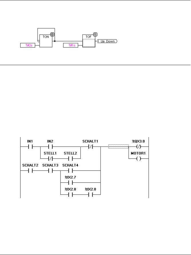
Example of a network in the Function Block Diagram
CoDeSys V2.3 |
2-21 |
Languages...
For further information on the FBD editor see Chapter 5.4.2.
2.2.5The Continuous Function Chart Editor (CFC)...
The continuous function chart editor does not operate like the function block diagram FBD with networks, but rather with freely placeable elements. This allows feedback, for example.
For further information on the CFC editor see Chapter 5.4.5
Example of a network in the continuous function chart editor
2.2.6Ladder Diagram (LD)...
The Ladder Diagram is also a graphics oriented programming language which approaches the structure of an electric circuit.
On the one hand, the Ladder Diagram is suitable for constructing logical switches, on the other hand one can also create networks as in FBD. Therefore the LD is very useful for controlling the call of other POUs.
The Ladder Diagram consists of a series of networks. A network is limited on the left and right sides by a left and right vertical current line. In the middle is a circuit diagram made up of contacts, coils, and connecting lines.
Each network consists on the left side of a series of contacts which pass on from left to right the condition "ON" or "OFF" which correspond to the Boolean values TRUE and FALSE. To each contact belongs a Boolean variable. If this variable is TRUE, then the condition is passed from left to right along the connecting line. Otherwise the right connection receives the value OFF.
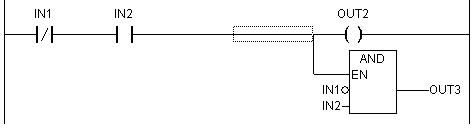
Example of a network in a Ladder Diagram made up of contacts and coils
For further information on the LD editor see Chapter 5.4.3.
Contact
Each network in LD consists on the left side of a network of contacts (contacts are represented by two parallel lines: | |) which from left to right show the condition "On" or "Off".
These conditions correspond to the Boolean values TRUE and FALSE. A Boolean variable belongs to each contact. If this variable is TRUE, then the condition is passed on by the connecting line from left to right, otherwise the right connection receives the value "Out".
2-22 |
CoDeSys V2.3 |
2 - What is What in CoDeSys
Contacts can be connected in parallel, then one of the parallel branches must transmit the value "On" so that the parallel branch transmits the value "On"; or the contacts are connected in series, then contacts must transmit the condition "On" so that the last contact transmits the "On" condition. This therefore corresponds to an electric parallel or series circuit.
A contact can also be negated, recognizable by the slash in the contact symbol: |/|. Then the value of the line is transmitted if the variable is FALSE.
Coil
On the right side of a network in LD there can be any number of so-called coils which are represented by parentheses:( ). They can only be in parallel. A coil transmits the value of the connections from left to right and copies it in an appropriate Boolean variable. At the entry line the value ON (corresponds to the Boolean variable TRUE) or the value OFF (corresponding to FALSE) can be present.
Contacts and coils can also be negated (in the example the contact SWITCH1 and the coil %QX3.0 is negated). If a coil is negated (recognizable by the slash in the coil symbol: (/)), then it copies the negated value in the appropriate Boolean variable. If a contact is negated, then it connects through only if the appropriate Boolean value is FALSE.
Function blocks in the Ladder Diagram
Along with contacts and coils you can also enter function blocks and programs In the network they must have an input and an output with Boolean values and can be used at the same places as contacts, that is on the left side of the LD network
Set/Reset coils
Coils can also be defined as set or reset coils. One can recognize a set coil by the "S" in the coil symbol: (S)) It never writes over the value TRUE in the appropriate Boolean variable. That is, if the variable was once set at TRUE, then it remains so.
One can recognize a reset coil by the "R" in the coil symbol: (R)) It never writes over the value FALSE in the appropriate Boolean variable: If the variable has been once set on FALSE, then it remains so.
LD as FBD
When working with LD it is very possible that you will want to use the result of the contact switch for controlling other POUs. On the one hand you can use the coils to put the result in a global variable which can then be used in another place. You can, however, also insert the possible call directly into your LD network. For this you introduce a POU with EN input.
Such POUs are completely normal operands, functions, programs, or function blocks which have an additional input which is labeled with EN. The EN input is always of the BOOL type and its meaning is: The POU with EN input is evaluated when EN has the value TRUE.
An EN POU is wired parallel to the coils, whereby the EN input is connected to the connecting line between the contacts and the coils. If the ON information is transmitted through this line, this POU will be evaluated completely normally.
Starting from such an EN POU, you can create networks similar to FBD.
Example of a LD network with an EN POU
CoDeSys V2.3 |
2-23 |