

8 - DDE Interface
8 DDE Interface
DDE Communication with CoDeSys
CoDeSys has a DDE (dynamic data exchange) interface for reading data. CoDeSys uses this interface to provide other applications that also use a DDE Interface with the contents of control variables and IEC addresses
If the GatewayDDEServer is used, which works with symbols, CoDeSys is not needed to read variables values from the PLC and to transfer them to applications with an DDE interface.
Attention: Direct addresses cannot be read over the DDE server ! For this case you have to define variables in CoDeSys which are assigned to the desired addresses (AT).
Attention: Direct addresses cannot be read via the DDE Server! For this case in CoDeSys variables with the appropriate address assignment (AT) have to be declared.
Attention: The DDE interface has been tested with Word 97 and Excel 97 on Windows NT 4.0. If the DDE communication fails caused by a mismatch of other versions or additionally installed programs on a computer, 3S – Smart Software Solutions cannot take any responsibility.
8.1DDE interface of the CoDeSys programming system...
Activating the DDE Interface
The DDE interface becomes active as soon as the PLC (or the simulation) is logged in.
General Approach to Data
A DDE inquiry can be divided into three parts:
1.Name of the program (here: CoDeSys),
2.File name and
3.Variable name to be read.
Name of the program: CoDeSys
File name: complete project path (c:\example\example.pro).
Variable name: The name of a variable as it appears in the Watch and Receipt Manager .
Which variables can be read?
All addresses and variables are readable. Variables or addresses should be entered in the format used in the Watch and Receipt Manager
Examples:
%IX1.4.1 |
(* Reads the input 1.4.1*) |
PLC_PRG.TEST (* Reads the variable TEST from the POU PLC_PRG*)
.GlobVar1 |
(* Reads the global variable GlobVar1 *) |
Linking variables using WORD
In order to get the current value of the variable TEST from the POU PLC_PRG through the DDE interface in Microsoft WORD, a field (e.g., the date) must be inserted in WORD ('Insert' "Field"). Now when you click on the field with the right mouse button and select the command "Toggle Field Codes" you can change the field function for the chosen text. In our example, this would look as follows:
{ DDEAUTO CODESYS "C:\CODESYS\PROJECT\IFMBSP.PRO" "PLC_PRG.TEST" }
Click on the field with the right mouse button again, then click on "Update Field" and the desired variable content appears in the text.
CoDeSys V2.3 |
8-1 |
DDE communcation with the GatewayDDE Server...
Linking variables using EXCEL
The following must be entered in Microsoft EXCEL before you can assign a variable to a cell.
=CODESYS|'C:\CODESYS\PROJECT\IFMBSP.PRO'!PLC_PRG.TEST'
When you click on 'Edit' then "Links", the result for this link will be:
Type: CODESYS
Source file: C:\CODESYS\PROJECT\IFMBSP.PRO
Element: PLC_PRG.TEST
Accessing variables with Intouch
Link with your project a DDE Access Name <AccessName> with the application name CODESYS and the DDE topic name C:\CODESYS\PROJECT\IFMBSP.PRO.
Now you can associate DDE type variables with the access name <AccessName>. Enter the name of the variable as the Item Name (e.g., PLC_PRG.TEST).
8.2DDE communcation with the GatewayDDE Server...
Handling of the GatewayDDE Server
The GatewayDDE Server can use the symbols which are created in CoDeSys for a project to communicate with other clients or the PLC. (see 'Project' 'Options' 'Symbolconfiguration'). It can serve the DDE interfaces of applications like e.g. Excel. This allows to transmit the variables values of the PLC to an applications, e.g. for the purpose of monitoring.
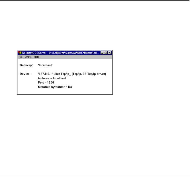
At start of the GatewayDDE Server a window opens, where the configuration of start and communication parameters can be done. A already existing configuration file can be called or the parameters can be set newly.
Starting dialog of the GatewayDDE Server
Using the command 'File' 'Open' you can call an already existing file which stores a set of configuration parameters. The standard dialog for selecting a file will open and available files with the extension ".cfg" will be offered. If a configuration file is selected, the configuration parameters and the defined target device are displayed
If the option 'File' 'Autoload' is activated, the GatewayDDE Server automatically opens with that configuration, which was active before the last terminating of the server.
If the server is started without any predefined configuration and without the setting Autoload, then in the configuration window 'Gateway:' und 'Device:' are displayed. Then you have to set up a new configuration.
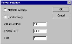
The command 'File' 'Settings' opens the dialog 'Server settings', in which the following parameters can be set:
8-2 |
CoDeSys V2.3 |
8 - DDE Interface
Dialog for configuring the GatewayDDE Server
Motorola byteorder |
Motorola Byteorder used |
Check identity |
It will be checked, whether the project ID given by the symbol file is the same |
|
as that stored in the PLC. |
Updaterate [ms] |
Time interval for reading all symbol values from the PLC. |
Timeout [ms] |
Communication timeout for the used driver. |
Tries |
Number of retries of the communication driver to transfer a data block (not |
|
supported by all drivers !) |
To set up the connection to the Gateway, the dialog 'Communication Parameters' is opened by the command 'Online' 'Parameters'. It is the same dialog as you get in CoDeSys with the command 'Online' 'Communication parameters'. The settings you do here must be the same as in the corresponding CoDeSys Project.
The actual configuration of the GatewayDDE Server can be stored in a file by the command 'File' 'Save'. The standard dialog for saving a file will open, default for the extension of the file is *.cfg.
To get the gateway in active mode, log in by the command 'Online' 'Login'. (The gateway symbol in the status bar will get lightened then.) At login the desired connection will be built up and the available symbols can be accessed.. These must have been created before in the CoDeSys Project!
To log out use the command 'Online' Logout'.
General Approach to Data
A DDE inquiry can be divided into three parts:
1.Name of the program (here: CoDeSys),
2.File name and
3.Variable name to be read.
Name of the program: CoDeSys
File name: complete project path (c:\example\example.pro).
Variable name: The name of a variable as it appears in the Watch and Receipt Manager .
Which variables can be read?
All addresses and variables are readable. Variables or addresses should be entered in the format used in the Watch and Receipt Manager
Examples: |
|
%IX1.4.1 |
(* Reads the input 1.4.1*) |
PLC_PRG.TEST |
(* Reads the variable TEST from the POU PLC_PRG*) |
.GlobVar1 |
(* Reads the global variable GlobVar1 *) |
CoDeSys V2.3 |
8-3 |

DDE communcation with the GatewayDDE Server...
Linking variables using WORD
Start the GatewayDDEServer before activating the inquiry in WORD.
In order to get the current value of the variable TEST from the POU PLC_PRG through the DDE interface in Microsoft WORD, a field (e.g., the date) must be inserted in WORD ('Insert' "Field"). Now when you click on the field with the right mouse button and select the command "Toggle Field Codes" you can change the field function for the chosen text. In our example, this would look as follows:
{ DDEAUTO GATEWAYDDESERVER "BSP.PRO" "PLC_PRG.TEST" }
Click on the field with the right mouse button again, then click on "Update Field" and the desired variable content appears in the text.
Linking variables using EXCEL
Start the GatewayDDEServer before activating the inquiry in EXCEL.
The following must be entered in Microsoft EXCEL before you can assign a variable to a cell.
=GATEWAYDDESERVER|<Dateiname>!<Variablenname>
Beispiel:
=GATEWAYDDESERVER|'bsp.pro'!'PLC_PRG.TEST'
When you click on 'Edit' then "Links", the result for this link will be:
Type: CODESYS
Source file: C:\CODESYS\PROJECT\IFMBSP.PRO
Element: PLC_PRG.TEST
{ DDEAUTO GATEWAYDDESERVER "BSP.PRO" "PLC_PRG.TEST" }
Command line options for the GatewayDDEServer
If the GatewayDDE Server is started by a command line, the following options can be attached:
/n |
The info dialog does not appear |
|
|
|
automatically at starting |
|
|
/s |
Display of the dialog window |
/s=h |
No |
|
|
/s=i |
minimized (icon) |
|
|
/s=m |
maximized |
|
|
/s=n |
normal |
/c |
Configuration file to be load automatically l |
/c=<config- |
|
|
|
file> |
|
/o |
Go online with the selected configuration |
|
|
|
(autoload or defined by "/c=") |
|
|
Example: Command line:
GATEWAYDDE /s=i /c="D:\DDE\conf_1.cfg"
The GatewayDDE Server will be started, the dialog window will appear as an icon, the configuration which is stored in the file conf_1.cfg will be loaded.
8-4 |
CoDeSys V2.3 |