


Languages...
Note: The programmer must make sure that no endless loop is caused. He does this by changing the condition in the instruction part of the loop, for example, by counting up or down one counter.
Example:
WHILE counter<>0 DO
Var1 := Var1*2;
Counter := Counter-1;
END_WHILE
The WHILE and REPEAT loops are, in a certain sense, more powerful than the FOR loop since one doesn't need to know the number of cycles before executing the loop. In some cases one will, therefore, only be able to work with these two loop types. If, however, the number of the loop cycles is clear, then a FOR loop is preferable since it allows no endless loops.
REPEAT loop
The REPEAT loop is different from the WHILE loop because the break-off condition is checked only after the loop has been executed. This means that the loop will run through at least once, regardless of the wording of the break-off condition.
Syntax:
REPEAT
<Instructions>
UNTIL <Boolean expression>
END_REPEAT;
The <Instructions> are carried out until the <Boolean expression> returns TRUE.
If <Boolean expression> is produced already at the first TRUE evaluation, then <Instructions> are executed only once. If <Boolean_expression> never assumes the value TRUE, then the <Instructions> are repeated endlessly which causes a relative time delay.
Note: The programmer must make sure that no endless loop is caused. He does this by changing the condition in the instruction part of the loop, for example by counting up or down one counter.
Example:
REPEAT
Var1 := Var1*2;
Counter := Counter-1;
UNTIL
Counter=0
END_REPEAT;
EXIT instruction
If the EXIT instruction appears in a FOR, WHILE, or REPEAT loop, then the innermost loop is ended, regardless of the break-off condition.
2.2.3Sequential Function Chart (SFC)...
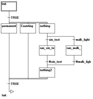
The Sequential Function Chart (SFC) is a graphically oriented language which makes it possible to describe the chronological order of different actions within a program. For this the actions are assigned to step elements and the sequence of processing is controlled by transition elements.
2-16 |
CoDeSys V2.3 |
2 - What is What in CoDeSys
Example for a network in the Sequential Function Chart
For further information on the SFC Editor see Chapter 5.4.4.
Step
A POU written in a Sequential Function Chart consists of a series of steps which are connected with each other through directed connections (transitions).
There are two types of steps.
•The simplified type consists of an action and a flag which shows if the step is active. If the action of a step is implemented, then a small triangle appears in upper right corner of the step.
•An IEC step consists of a flag and one or more assigned actions or boolean variables. The associated actions appear to the right of the step.
Action
An action can contain a series of instructions in IL or in ST, a lot of networks in FBD or in LD, or again in Sequential Function Chart (SFC).
With the simplified steps an action is always connected to a step. In order to edit an action, click twice with the mouse on the step to which the action belongs. Or select the step and select the menu command 'Extras' 'Zoom Action/Transition'. In addition, one input or output action per step is possible.
Actions of IEC steps hang in the Object Organizer directly under their SFC-POU and are loaded with a double-clickor by pressing <Enter> in their editor. New actions can be created with 'Project' 'Add Action'. You can assign max. nine actions to one IEC step.
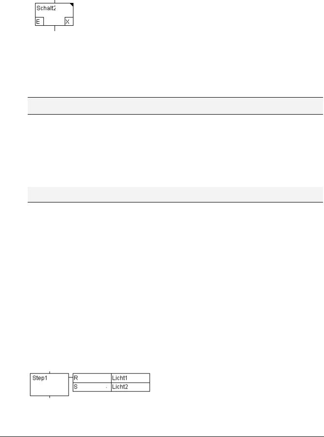
Entry or exit action
Additional to a step action you can add an entry action and an exit action to a step. An entry action is executed only once, right after the step has become active. An exit action is executed only once before the step is deactivated.
A step with entry action is indicated by an "E" in the lower left corner, the exit action by an "X" in the lower right corner.
CoDeSys V2.3 |
2-17 |
Languages...
The entry and exit action can be implemented in any language. In order to edit an entry or exit action, double-clickin the corresponding corner in the step with the mouse.
Example of a step with entry and exit action:
Transition / Transition condition
Between the steps there are so-called transitions.
A transition condition must have the value TRUE or FALSE. Thus it can consist of either a boolean variable, a boolean address or a boolean constant. It can also contain a series of instructions having a boolean result, either in ST syntax (e.g. (i<= 100) AND b) or in any language desired (see 'Extras' 'Zoom Action/Transition'). But a transition may not contain programs, function blocks or assignments!
Note: Besides transitions, inching mode can also be used to skip to the next step; see SFCtip and SFCtipmode.
Active step
After calling the SFC POU, the action (surrounded by a double border) belonging to the initial stepis executed first. A step, whose action is being executed, is called active. In Online mode active steps are shown in blue.
In a control cycle all actions are executed which belong to active steps. Thereafter the respective following steps of the active steps become active if the transition conditions of the following steps are TRUE. The currently active steps will be executed in the next cycle.
Note: If the active step contains an output action, this will only be executed during the next cycle, provided that the transition following is TRUE.
IEC step
Along with the simplified steps the standard IEC steps in SFC are available.
In order to be able to use IEC steps, you must link the special SFC library lecsfc.lib into your project.
Not more than nine actions can be assigned to an IEC step. IEC actions are not fixed as input, step or output actions to a certain step as in the simplified steps, but are stored separately from the steps and can be reused many times within a POU. For this they must be associated to the single steps with the command 'Extras' 'Associate action'.
Along with actions, Boolean variables can be assigned to steps.
The activation and deactivation of actions and boolean variables can be controlled using so-called qualifiers. Time delays are possible. Since an action can still be active, if the next step has been processed, for example through the qualifier S (Set), one can achieve concurrent processes.
An associated boolean variable is set or reset with each call of the SFC block. That means, that with each call the value changes from TRUE or FALSE or back again.
The actions associated with an IEC step are shown at the right of the step in a two-part box. The left field contains the qualifier, possibly with time constant, and the right field contains the action name respectively boolean variable name.
An example for an IEC step with two actions:
In order to make it easier to follow the processes, all active actions in online mode are shown in blue like the active steps. After each cycle a check is made to see which actions are active.
2-18 |
CoDeSys V2.3 |
2 - What is What in CoDeSys
Pay attention here also to the restrictions on the use of time-qualifiers in actions that are repeatedly re-used within the same cycle (see 'Qualifier') !
Note: If an action has been inactivated, it will be executed once more. That means, that each action is executed at least twice (also an action with qualifier P).
In case of a call first the deactivated actions, then the active actions are executed, in alphabetical order each time.
Whether a newly inserted step is an IEC step depends upon whether the menu command 'Extras' 'Use IEC-Steps' has been chosen.
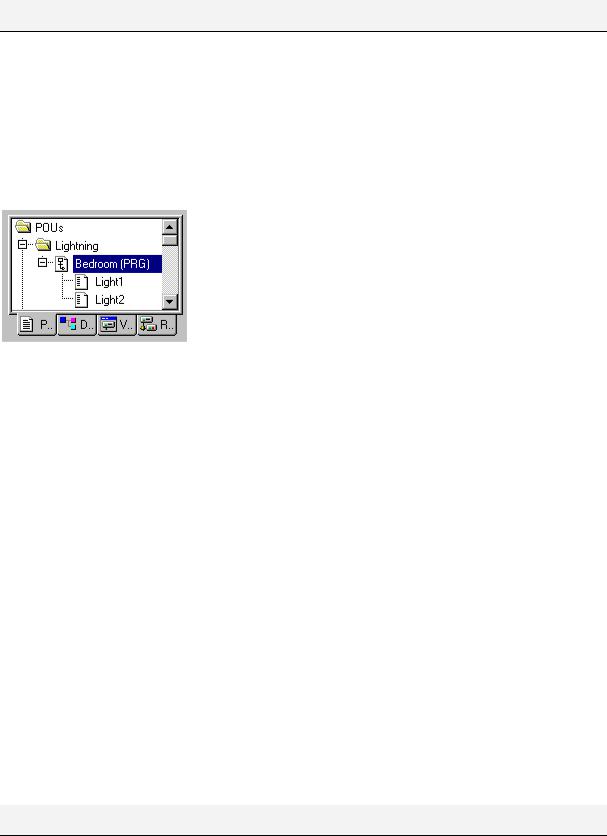
In the Object Organizer the actions hang directly underneath their respective SFC POUs. New actions can be created with 'Project' 'Add Action'.
In order to use IEC steps you must include in your project the special SFC library Iecsfc.lib .
SFC POU with actions in the Object Organizer
Qualifier
In order to associate the actions with IEC steps the following qualifiers are available:
N |
Non-stored |
The action is active as long as the step |
R |
overriding Reset |
The action is deactivated |
S |
Set (Stored) |
The action is activated and remains active until a |
|
|
Reset |
L |
time Limited |
The action is activated for a certain time, maximum |
|
|
as long as the step is active |
D |
time Delayed |
The action becomes active after a certain time if the |
|
|
step is still active and then it remains active as long |
|
|
as the step is active. |
P |
Pulse |
The action is executed just one time if the step is |
|
|
active |
SD |
Stored and time |
The action is activated after a certain time and |
|
Delayed |
remains active until a Reset |
DS |
Delayed and Stored |
The action is activated after a certain time as long |
|
|
as the step is still active and remains active up to a |
|
|
Reset |
SL |
Stored and time |
The action is activated for a certain time |
|
limited |
|
The qualifiers L, D, SD, DS and SL need a time value in the TIME constant format.
Note: When an action has been deactivated it will be executed once more. This means that each action at least is executed twice (also an action with qualifier P).
CoDeSys V2.3 |
2-19 |

Languages...
Implicit variables in SFC
There are implicitly declared variables in the SFC which can be used.
A flag belongs to each step which stores the state of the step. The step flag (active or inactive state of the step) is called <StepName>.x for IEC steps or <StepName> for the simplified steps. This Boolean variable has the value TRUE when the associated step is active and FALSE when it is inactive. It can be used in every action and transition of the SFC block.
One can make an enquiry with the variable <ActionName>.x. as to whether an IEC action is active or not.
For IEC steps the implicit variables <StepName>.t can be used to enquire about the active time of the steps.
Implicit variables can also be accessed by other programs. Example: boolvar1:=sfc1.step1.x; Here, step1.x is the implicit boolean variable representing the state of IEC step step1 in POU sfc1.
SFC Flags
For controlling the operation of SFC POUs flags can be used, which are created implicitely during running the project. To read this flags you have to define appropriate global or local variables as inputs or outputs. Example: If in a SFC POU a step is active for a longer time than defined in the step attributes, then a flag will be set, which is accessible by using a variable "SFCError" (SFCError gets TRUE in this case).
The following flag variables can be defined:
SFCEnableLimit: This variable is of the type BOOL. When it has the value TRUE, the timeouts of the steps will be registered in SFCError. Other timeouts will be ignored.
SFCInit: When this boolean variable has the value TRUE the sequential function chart is set back to the Init step. The other SFC flags are reset too (initialization). The Init step remains active, but is not executed, for as long as the variable has the value TRUE. It is only when SFCInit is again set to FALSE that the block can be processed normally.
SFCReset: This variable, of type BOOL, behaves similarly to SFCInit. Unlike the latter, however, further processing takes place after the initialization of the Init step. Thus for example the SFCReset flag could be re-set to FALSE in the Init step.
SFCQuitError: Provided that the Execution of the SFC diagram is stopped for as long as this boolean variable has the value TRUE whereby a possible timeout in the variable SFCError is reset. All previous times in the active steps are reset when the variable again assumes the value FALSE. It is a pre-condition that the flag SFCError has been defined also, which registers any timeout in the SFC.
SFCPause: Execution of the SFC diagram is stopped for as long as this boolean variable has the value TRUE.
SFCError: This Boolean variable is TRUE when a timeout has occurred in a SFC diagram. If another timeout occurs in a program after the first one, it will not be registered unless the variable SFCError is reset first. It is a pre-condition that SFCError is defined, if you want to use the other time-controlling flags (SFCErrorStep, SFCErrorPOU, SFCQuitError, SFCErrorAnalyzation).
SFCTrans: This boolean variable takes on the value TRUE when a transition is actuated.
SFCErrorStep: This variable is of the type STRING. If SFCError registers a timeout, in this variable is stored the name of the step which has caused the timeout. It is a pre-condition that the flag SFCError has been defined also, which registers any timeout in the SFC.
SFCErrorPOU: This variable of the type STRING contains the name of the block in which a timeout has occurred. It is a pre-condition that the flag SFCError has been defined also, which registers any timeout in the SFC.
SFCCurrentStep: This variable is of the type STRING. The name of the step is stored in this variable which is active, independently of the time monitoring. In the case of simultaneous sequences the step is stored in the branch on the outer right. No further timeout will be registered if a timeout occurs and the variable SFCError is not reset again.
2-20 |
CoDeSys V2.3 |