

6 - The Resources
6.6.9Configuration of a CanDevice (CANopen Slave)
A PLC which is programmable with CoDeSys can be used as a CANopen Slave (CANopen-Node, called "CanDevice" in the following) in a CAN network.
For this purpose the PLC can be configured in the CoDeSys PLC Configurator and the configuration can be saved in an EDS-file. This EDS-file (device file) later can be used in any CANopen Master configuration.
Preconditions for creating a CanDevice in the CoDeSys PLC Configurator: 1. The libraries
3S_CanDrv.lib
3S_CanOpenManager.lib
3S_CanOpenDevice.lib
must be included in the CoDeSys project. They are needed for running the PLC as an CANopen device.
2. In the configuration file (*.cfg) on which the configuration is basing, an appropriate entry for a CanDevice must be inserted. Only then in the PLC Configuration Editor a subelement 'CanDevice' can be appended and parameterized in the three configuration dialogs which will be described in the following:
Base settings CAN settings
Default PDO mapping
Base settings of a CanDevice
Dialog Base settings
Bus identifier: currently not used.
Name of updatetask: Name of the task, in which the CanDevice is called. A selection list will provide all tasks which are available in the project.
EDS file generation: Activate this option if you want to generate a device file (EDS file) from the current configuration settings in order to be able to use the CanDevice later in any master configuration. Enter a path and name for the file in the field Name of EDS file. Optionally a manually created template file can be defined (Template for EDS file), which will be supplemented with the settings done in the configuration dialogs. For example you could create a text file containing certain EDS file entries, save it as "EDS_template.txt" and enter the path of this template in the current dialog.
CoDeSys V2.3 |
6-41 |
PLC Configuration...
If you then generate an EDS file "device_xy.eds" from the current project, the entries resulting from the project will be merged with those of the template and will be saved in "device_xy.eds". (Do not use the extension ".eds" for the template file !) If entries are created by the current project which are already defined by the template, the template definitions will not be overwritten.
For entering the file paths you can use the standard dialog for browsing for a file which can be opened by using the button Browse....
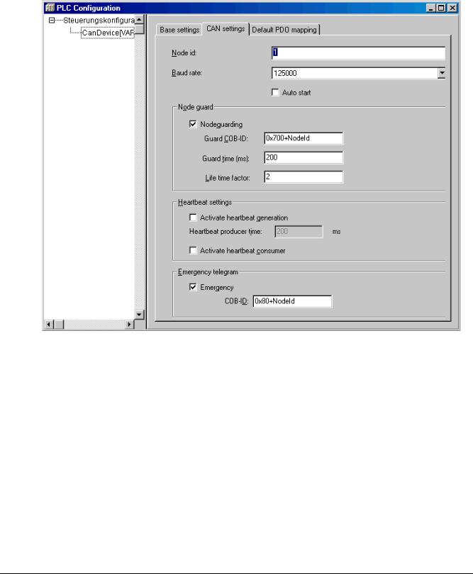
CAN settings of a CanDevice
Dialog CAN settings
Here you can set the Node id and the Baud rate. The node id is a node number which is used by the master for addressing the device in a CANopen network.
A configuration of Nodeguarding, Heartbeat and Emergency Telegram functionality is possible.
Please see the corresponding descriptions for the configuration of CAN modules and masters. Heartbeat is currently not supported.
6-42 |
CoDeSys V2.3 |
6 - The Resources
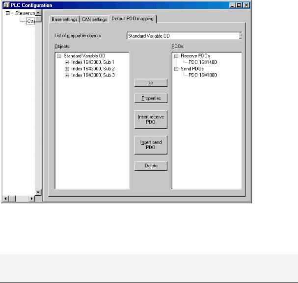
Default PDO mapping of a CanDevice
Dialog Default PDO mapping
In this dialog the entries of the local Parameter Manager can be assigned to PDOs, which will be sent/received by the CanDevice. The PDOs then will be available for the PDO mapping in any master configuration where the CanDevice is integrated.
In the Parameter Manager lists the parameter entries are linked to project variables via index/subindex.
Please regard: Subindex 0 of an index, which implies more than one subindex, will be used implicitly for storing the number of subindices. For this reason do not use subindex 0 in the Parameter Manager. Also regard that the parameters of a particular index must be entered in ascending order (subindices 1,2,3...) in the Parameter Manager.
List of mapable objects: Choose from the selection list the variables' parameter list, for whose entries the CanDevice should generate PDOs. If supported by the target system, parameter lists of type 'Mapping' can be created in the Parameter Manager, which contain process variables especially intended for the PDO mapping of a CANDevice. In this case only these parameter lists will be offered here in the mapping dialog. Otherwise all available parameter lists of type 'Variables' and 'Instance' will be offered.
According to the chosen parameter list the Objects will appear in the left window. In the right window you create the desired PDO configuration (PDO's). Via the buttons Insert receive PDO resp. Insert send PDO there you can insert 'Receive PDOs' and 'Send PDOs' below the corresponding list organizing elements. In order to assign an object of the left window to one of these send or receive PDOs, mark the object in the left window and also the PDO in the right window and then press >>. Thereupon the object will be inserted below the PDO in the right window. The Properties of the PDO can be defined in a dialog which is also used for the PDO configuration of other CAN modules.
By using button Delete the PDO currently marked in the right window will be removed from the configuration.
CoDeSys V2.3 |
6-43 |

PLC Configuration...
Example:
objective: On the first Receive PDO (COB-Id = 512 + NodeId) of the CanDevice the variable PLC_PRG.a should be received.
Thus in the Parameter Manager in a variable list a index/subIndex must be assigned to variable PLC_PRG.a. The Parameter Manager can only be opened, if it is activated in the target settings in category 'Network functionality' and if valid index and subindex ranges are defined there.
Now in the dialog 'Default PDO-Mapping' of the CanDevice the index/subindex entry of the respective parameter list can be assigned to a Receive PDO,
6.6.10PLC Configuration in Online Mode
In online mode the PLC configuration displays the states of the inputs and outputs of the PLC. If a boolean input or output has the value TRUE, the little box at the beginning of the entry line in the configuration tree will get blue, non-boolean values will be added at the end of the entry line (e.g. "=12").
The boolean inputs can be toggled by mouse-clicks. At other inputs a mouse-click on the beginning of the line opens a dialog, where the value can be modified. The modified value will be set in the PLC as soon as the dialog is closed with OK.
Also regard the target specific possibilities for online diagnosis.
6.6.11Hardware scan/State/Diagnosis information from the PLC
If supported by the target system and the actual configuration file (*.cfg), information on the structure, the status and diagnosis results of the currently connected hardware can be get from the PLC and displayed in the PLC Configuration in CoDeSys:
Scan module configuration
If supported by the target system and the actual configuration file (*.cfg), the command Scan module configuration will be available in the context menu for the module which is currently selected in the PLC Configuration tree.
This command is only available in offline mode. If it is activated, the actual hardware configuration of the particular module on the PLC will be scanned and automatically be offered for inserting in the configuration tree of the CoDeSys PLC Configuration. Thus the existing module configuration can easily be mapped in CoDeSys.
Load module state
If supported by the target system and the actual configuration file (*.cfg), the command Load module state will be available in the context menu for the module which is currently selected in the PLC Configuration tree.
This command is only available in online mode. If it is activated, the actual status of the module will be read from the PLC and get displayed by a special color in the configuration tree:
Black: Module existing and parameterized correctly. Blue: Module existing but parameterized incorrectly. Red: Module not found.
An update of the status display also automatically will be done at each download.
Show diagnosis messages
If supported by the target system and the actual configuration file (*.cfg), the command Show diagnosis messages will be available in the context menu for the module which is currently selected in the PLC Configuration tree. This command is only available in online mode. If it is activated, actual diagnosis messages for the module coming from the PLC will be displayed in a CoDeSys window.
6-44 |
CoDeSys V2.3 |