

PLC Configuration...
The log that is present in the project will not be overwritten by the command. If the log window is closed and later opened again, or a new Online session is started then the version that is loaded will again be replaced by the project log.
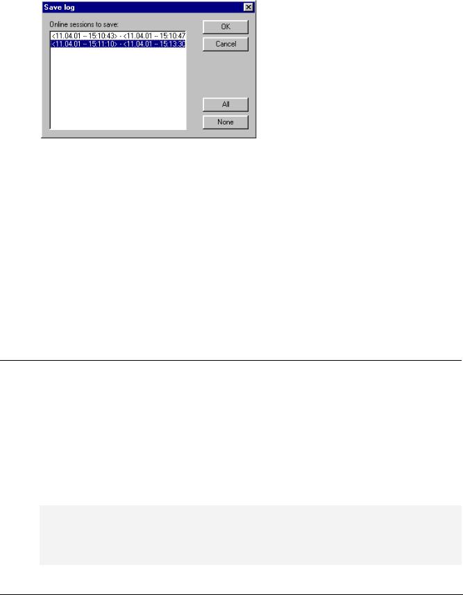
Save… This menu item can only be selected if the project log is currently displayed. It allows an excerpt of the project log to be stored in an external file. For that, the following dialog will be displayed, in which the Online sessions to be stored can be selected:
After successful selection, the standard dialog for storing a file opens ('Save Log').
Display Project Log This command can only be selected if an external log is currently displayed. It switches the display back to the project log.
Storing the project log
Regardless of whether or not the log is stored in an external file (see above), the project log is automatically stored in a binary file entitled <projectname>.log. If a different path is not explicitly given in the 'Project' 'Options' 'Log' dialog, the file is stored in the same directory as that in which the project is stored.
The maximum number of Online sessions to be stored can be entered in the 'Project' 'Options' 'Log' dialog. If this number is exceeded during recording, the oldest session is deleted to make room for the newest one.
6.6PLC Configuration...
6.6.1Overview
The  PLC Configuration is found as an object in the register card Resources in the Object Organizer. With the PLC Configuration editor, you must describe the hardware the opened project is established for. For the program implementation, the number and position of the inputs and outputs is especially important. With this description, CoDeSys verifies whether the IEC addresses used in the program also actually exist in the hardware.
The base of working in the configuration editor is/are the configuration files (*.cfg; see below Note concerning version compatibility') and the device files (.e.g. *.gsd, *.eds). These are stored in the directory which is defined in the target file (see Target Settings) and are read when the project is opened in CoDeSys. You can add files to this directories at any time.
The configuration file *.cfg describes a basic configuration, which is mapped in the configuration editor, and it defines to which extent the user can customize this configuration in the editor.
Attention: As soon as the underlying configuration file (*.cfg) has been modified, you have to redo the configuration in CoDeSys!
Note concerning version compatibility: In CoDeSys V2.2 a new format was implemented for the PLC Configuration. From that version on the basic configuration files have to use the extension *.cfg. In contrast the configuration editor in former CoDeSys versions needed configuration files with an extension *.con. But: In the target file you can determine that the "old" configurator should be used
6-20 |
CoDeSys V2.3 |
6 - The Resources
furtheron, even when an old project is opened in V2.2 or higher. This avoids the necessarity to create new configuration files, the *.con-files can be used furtheron. If this option is not set in the target file, then you can convert the old PLC Configuration, which is stored in the project, to the new format, if (!) an appropriate new *.cfg-file has been provided. See more details in 'Extras' 'Convert'.
The CoDeSys configuration editor allows configuring I/O modules as well as CAN and Profibus modules.
If supported by the target system, there is the possibility to get information from the PLC: 1. a scan of the actual hardware structure which can directly be used in the PLC Configuration, 2. diagnosis messages which will be displayed as messages in CoDeSys, 3. status information which will be displayed in the PLC Configuration dialog
After the final customization by the user a binary image of the configuration is sent to the PLC:
Example PLC Configuration with a CPU Module and a CAN Module
The PLC Configuration is displayed in the editor in tree structure and can be edited using menu commands and dialogs. The configuration contains input and/or output elements and also management elements which themselves also have sub elements (for example, a CAN-bus or a digital input card with 8 inputs).
For inputs and outputs, symbolic names can be assigned. The IEC-address where this input or output can be accessed is then located behind the symbolic name.
6.6.2Working in the PLC Configuration...
The configuration editor is divided up in two parts. In the left window the configuration tree is displayed. Structure and components of the tree result primarily (Standardconfiguration) from the definitions found in the configuration file, but can be modified by the additional adaptation which is done by the user in the CoDeSys PLC Configurator. In the right window the currently available configuration dialogs are shown on one or several tabs.
The right part of the window is per default visible, but can get faded out via the menu item 'Extras' 'Properties'.
On top of the configuration tree there is the entry of the "root" module with a name, which has been defined in the configuration file.
Below you find hierarchically indented the other elements of the configuration: Modules of different types (CAN, Profibus, I/O), channels or bit channels.
The configuration editor is divided up in two parts. In the left window the configuration tree is displayed. Structure and components of the tree result primarily (Standardconfiguration) from the definitions found in the configuration file, but can be modified by the additional adaptation which is
CoDeSys V2.3 |
6-21 |

PLC Configuration...
done by the user in the CoDeSys PLC Configurator. In the right window the currently available configuration dialogs are shown on one or several tabs.
The right part of the window is per default visible, but can get faded out via the menu item 'Extras' 'Properties'.
On top of the configuration tree there is the entry of the "root" module with a name, which has been defined in the configuration file.
Below you find hierarchically indented the other elements of the configuration: Modules of different types (CAN, Profibus, I/O), channels or bit channels.
Selecting of elements
For selecting elements, click the mouse on the corresponding element, or, using the arrow keys, move the dotted rectangle onto the desired element.
Elements that begin with a plus sign are organization elements and contain sub elements. To open an element, select the element and double-click the plus sign or press <Enter>. You can close opened elements (minus sign in front of the element) the same way.
Insert elements, 'Insert' 'Insert element', 'Insert' 'Append subelement'
Depending on the definitions in the configuration file(s) and on the available device files, which have been read when the project was opened, a basic composition of elements is automatically positioned in the configuration tree. If one of those elements is selected, further elements may be added if this is allowed by the definitions in the configuration file and if the needed device files are available:
•'Insert' 'Insert element': An element can be selected and inserted before the element which is currently marked in the configuration tree.
•'Insert' 'Append subelement': An element can be selected and inserted as subelement of the element which is currently marked in the configuration tree. It will be inserted at the last position.
The most important commands are found in the context menu (right mouse button or <Ctrl>+<F10>).
Please note: If supported by the target system, a scan of the existing hardware can be used for the inserting of modules in the CoDeSys PLC Configuration.
Replacing/switching Elements, 'Extras' 'Replace element''
Depending on the definition in the configuration file, the currently selected element may be get replaced by an other one. The same way it may be possible to switch channels, which are set up in a way that they can be used as input or as output elements. Use the command 'Extras' 'Replace element'
Symbolic names
Symbolic names for modules and channels can be defined in the configuration file. In this case they will be shown in the configuration editor before the 'AT' of the IEC address of the respective element. In the configuration file also is defined whether the symbolic name can be edited or inserted in the configuration editor. To enter a symbolic name, select the desired module or channel in the configuration tree and open a text field by a mouse-click on the 'AT' before the IEC address. In the same manner you can edit an existing symbolic name after a double-clickon the name. Please regard that allocating a symbolic name corresponds with a valid variable declaration !
6.6.3General Settings in the PLC Configuration
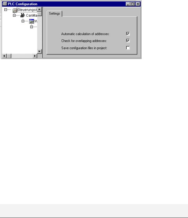
Select the entry 'PLC configuration' ('root' module) at top of the configuration tree. Thereupon the dialog 'Settings' is shown in the right part of the window. The following options can be activated:
Calculate addresses: Each newly inserted module automatically is allocated with an address, which results from the address of the module inserted before plus the size of this address. If a module is removed from the configuration, the addresses of the following modules are adjusted automatically. When the command 'Extras' 'Compute addresses' is executed, all addresses starting at the selected node (module) will be recalculated.
6-22 |
CoDeSys V2.3 |
6 - The Resources
Check for overlapping addresses: At compilation the project will be checked for overlapping addresses and a corresponding message will be displayed.
Save configuration files in project: The information which is contained in the configuration file(s) *.cfg and the device description files, which underlie the current PLC Configuration, will be saved in the project.
Thus (if it is not defined by the configuration file, that always the standard configuration should be reloaded !), the configuration as set up by the user will be kept in the project, even if configuration files are not found when the project is re-opened. Keep in mind that in such a case the complete project specific configuration will get lost, if the here described option is not activated !
By saving the configuration information with the project these also will be kept at a target change. But regard in this case, that the new target might bring own configuration files which then will be regarded additionally.
Dialog for the general Settings of the PLC configuration
The global mode of addressing (flat addresses / addresses depending on Id) in the PLC configuration is defined in the configuration file.
Recalculation of Module addresses, 'Extras' 'Compute addresses'
If the option "Calculate addresses" is activated in the dialog 'Settings' of the PLC configuration editor , then the command 'Extras' 'Compute addresses' will start to recalculate the addresses of the modules. All modules starting with the one, which is currently selected in the configuration tree, will be regarded.
Add configuration file
Use this command in the 'Extras' menu to add a further file to the configuration files of the project. These are the files which are found in the directory path(es) specified in the project options, category 'Directories', input field 'Configuration files'.
The dialog Select configuration file will be opened, where you can set a filter for CAN- (*.eds,*. dcf), Profibus- (gsd*.*), configuration- (*.cfg)-files or all files (*.*). After having selected the desired file a check will be done, whether the file is already found in one of the defined directories for configuration files. In this case an appropriate message will appear and the file cannot be added. If a cfg-file is selected, in each case an dialog will open where you get information on what to do.
If the file can be added, the dialog Select configuration directory, where all configuration directories currently defined for the project will appear in a selection list. Choose the directory where the file whereto the file should be copied. After having confirmed this selection by pressing button OK, the dialog will close and the file immediately will be available in the PLC configuration.
Return to standard configuration, 'Extras' 'Standard configuration'
The command 'Extras' 'Standardconfiguration' can be used to restore the original PLC configuration, which is defined by the configuration file *.cfg and saved in the project.
Attention: In the configuration file *.cfg it might be defined that the standard configuration should be restored at each reopening of the project. In this case all adaptations of the configuration done by the user will get lost !
CoDeSys V2.3 |
6-23 |