

The Graphic Editors...
Otherwise, the entire branch located in front of the pasting point will be replaced by the contents of the clipboard.
In each case, the last element pasted is connected to the branch located in front of the pasting point.
Note: The following problem is solved by cutting and pasting: A new operator is inserted in the middle of a network. The branch located on the right of the operator is now connected with the first input, but should be connected with the second input. You can now select the first input and perform the command 'Edit' 'Cut'. Following this, you can select the second input and perform the command 'Edit' 'Paste'. This way, the branch is dependent on the second input.
The Function Block Diagram in the Online Mode
In the Function Block Diagram, breakpoints can only be set to networks. If a breakpoint has been set to a network, then the network numbers field will be displayed in blue. The processing then stops in front of the network where the breakpoint is located. In this case, the network numbers field will become red. Using stepping (single step), you can jump from network to network.
The current value is displayed for each variable. Exception: If the input to a function block is an expression, only the first variable in the expression is monitored.
Doubleclicking on a variable opens the dialog box for writing a variable. Here it is possible to change the present value of the variable. In the case of Boolean variables, no dialog box appears; these variables are toggled.
The new value will turn red and will remain unchanged. If the 'Online' 'Write values' command is given, then all variables are placed in the selected list and are once again displayed in black.
The flow control is started with the 'Online' 'Flow control' command Using the flow control, you can view the present values that are being carried in the networks over the connecting lines. If the connecting lines do not carry Boolean values, then the value will be displayed in a specially inserted field. If the lines carry Boolean values, then they will be shaded blue in the event that they carry TRUE. By this means, you can accompany the flow of information while the PLC is running.
If you place the mouse pointer briefly above a variable, then the type, the address and the comment about the variable will be displayed in a Tooltip.
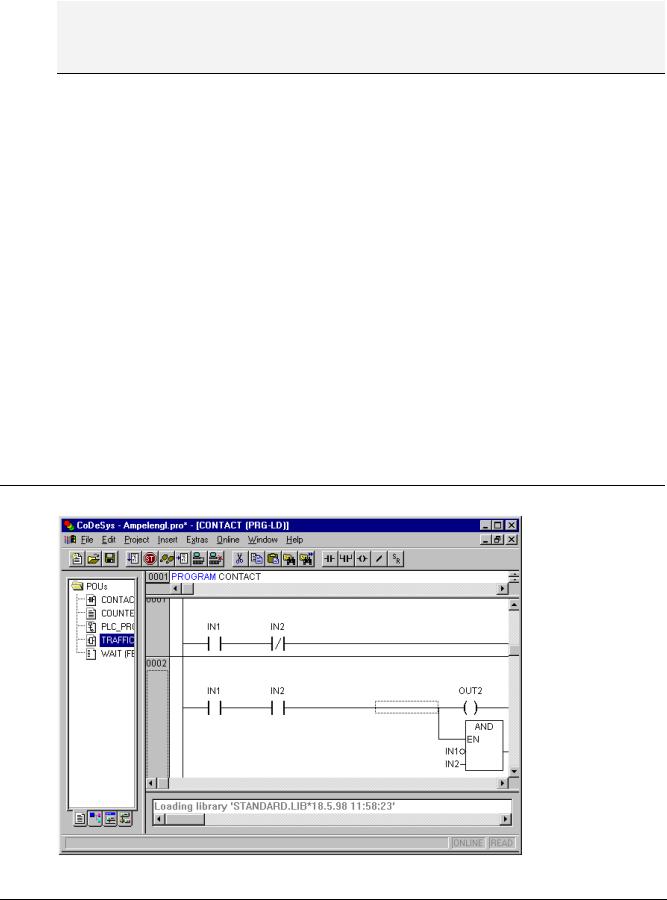
5.4.3The Ladder Editor...
This is how a POU written in the LD appears in the CoDeSys editor:
5-28 |
CoDeSys V2.3 |
5 - Editors in CoDeSys
All editors for POUs consist of a declaration part and a body. These are separated by a screen divider.
The LD editor is a graphic editor. The most important commands are found in the context menu (right mouse button or <Ctrl>+<F10>).
For information about the elements, see Chapter 2.2.6, Ladder Diagram (LD).
Cursor Positions in the LD Editors
The following locations can be cursor positions, in which the function block and program accessing can be handled as contacts. POUs with EN inputs and other POUs connected to them are treated the same way as in the Function Block Diagram. Information about editing this network part can be found in chapter 5.4.2, FBD Editor.
1.Every text field (possible cursor positions framed in black)
2.Every Contact or Function Block
3.Every Coil
4.The Connecting Line between the Contacts and the Coils.
The Ladder Diagram uses the following menu commands in a special way:
Move elements in the LD-Editor
An element can be moved to a different position within a LD POU by "drag&drop".
In order to do this select the desired element (contact, coil, function block) and drag it - keeping the mouse key pressed - away from the current position. Thereupon all possible positions within all networks of the POU, to which the element might be moved, will be indicated by grey-filled rectangles. Move the element to one of these positions and let off the mouse key: the element will be inserted at the new position.
CoDeSys V2.3 |
5-29 |
The Graphic Editors...
'Insert' 'Contact' in LD
Symbol:  Shortcut: <Ctrl>+<O>
Use this command in the LD editor in order to insert a contact in front of the marked location in the network.
If the marked position is a coil or the connecting line between the contacts and the coils, then the new contact will be connected serially to the previous contact connection.
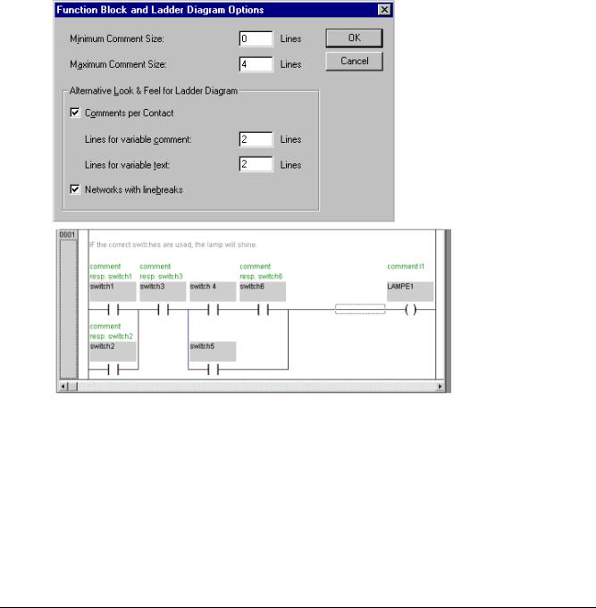
The contact is preset with the text "???". You can click on this text and change it to the desired variable or the desired constant. For this you can also use the Input Assistant. You can activate the options Comments per Contact and Lines for variable comment in the dialog 'Function Block and Ladder Diagram Options' ('Extras' 'Options') to reserve a certain number of lines for the variable name. This might be useful, if long variable names are used, to keep the network short.
Also regard the option Networks with linebreaks, which you also can activate in the Ladder Diagram Options.
Example for the options dialog and the resulting display in a FBD or Ladder network:
'Insert' 'Parallel Contact'
Symbol:  Shortcut: <Ctrl>+<R>
Use this command in the LD editor to insert a contact parallel to the marked position in the network.
If the marked position is a coil or the connection between the contacts and the coils, then the new contact will be connected in parallel to the entire previous contact connection.
The contact is preset with the text "???". You can click on this text and change it to the desired variable or the desired constant. For this you can also use the Input Assistant.
5-30 |
CoDeSys V2.3 |
5 - Editors in CoDeSys
It is possible to display the variable name with line breaks. Also a separate comment can be inserted for the contact. For a description see 'Insert' 'Contact' .
'Insert' 'Function Block' in LD Shortcut: <Ctrl>+<B>
Use this command in order to insert an operator, a function block, a function or a program as a POU. For this, the connection between the contacts and the coils, or a coil, must be marked. The new POU at first has the designation AND. If you wish, you can change this designation to another one. For this you can also use the Input Assistant. Both standard and self-defined POUs are available.
The first input to the POU is placed on the input connection, the first output on the output connection; thus these variables must definitely be of type BOOL. All other inand outputs of the POU are filled with the text „???". These prior entries can be changed into other constants, variables or addresses. For this you can also use the Input Assistant.
'Insert' 'Coil' in LD
Symbol:  Shortcut: <Ctrl>+<L>
You can use this command in the LD editor to insert a coil in parallel to the previous coils.
If the marked position is a connection between the contacts and the coils, then the new coil will be inserted as the last. If the marked position is a coil, then the new coil will be inserted directly above it.
The coil is given the text "???" as a default setting. You can click on this text and change it to the desired variable. For this you can also use the Input Assistant.
It is possible to display the variable name with line breaks. Also a separate comment can be inserted for the coil. For a description see 'Insert' 'Contact'
POUs with EN Inputs
If you want to use your LD network as a PLC for calling up other POUs , then you must merge a POU with an EN input. Such a POU is connected in parallel to the coils. Beyond such a POU you can develop the network further, as in the Function Block Diagram. You can find the commands for insertion at an EN POU under the menu item 'Insert' 'Insert at Blocks'.
An operator, a function block, a program or a function with EN input performs the same way as the corresponding POU in the Function Block Diagram, except that its execution is controlled on the EN input. This input is annexed at the connecting line between coils and contacts. If this connection carries the information "On", then the POU will be evaluated.
If a POU has been created once already with EN input, then this POU can be used to create a network. This means that data from usual operators, functions, and function blocks can flow in an EN POU and an EN POU can carry data to such usual POUs.
If, therefore, you want to program a network in the LD editor, as in FBD, you only need first to insert an EN operator in a new network. Subsequently, from this POU, you can continue to construct from your network, as in the FBD editor. A network thus formed will perform like the corresponding network in FBD.
'Insert' 'Box with EN in LD'
Use this command to insert a function block, an operator, a function or a program with EN input into a LD network.
The marked position must be the connection between the contacts and the coils (Cursor Position 4) or a coil (Cursor Position 3). The new POU is inserted in parallel to the coils and underneath them; it contains initially the designation "AND". If you wish, you can change this designation to another one. For this you can also use the Input Assistant.
CoDeSys V2.3 |
5-31 |

The Graphic Editors...
'Insert' 'Insert at Blocks in LD
With this command you can insert additional elements into a POU that has already been inserted (also a POU with EN input). The commands below this menu item can be executed at the same cursor positions as the corresponding commands in the Function Block Diagram.
With Input you can add a new input to the POU. With Output you can add a new output to the POU.
With POU, you insert a new POU. The procedure is similar to that described under 'Insert' 'POU'.
With Assign you can insert an assignment to a variable. At first, this is shown by three question marks „???", which you edit and replace with the desired variable. Input assistance is available for this purpose.
'Insert' 'Jump' in LD
With this command you can insert a parallel jump in the selected LD editor, in parallel, at the end of the previous coils. If the incoming line delivers the value "On", then the jump will be executed to the indicated label.
The marked position must be the connection between the contacts and the coilsor a coil.
The jump is present with the text "???". You can click on this text and make a change in the desired label.
'Insert' 'Return' in LD
In the LD editor, you can use this command to insert a Return instruction in parallel at the end of the previous coils. If the incoming line delivers the value "On," then the processing of the POU in this network is broken off.
The marked position must be the connection between the contacts and the coils or a coil.
'Extras' 'Paste after' in LD
Use this command in the LD editor to paste the contents of the clipboard as serial contact below the marked position. This command is only possible if the contents of the clipboard and the marked position are networks comprised of contacts.
'Extras' 'Paste below' in LD Shortcut: <Ctrl>+<U>
Use this command in the LD editor to insert the contents of the clipboard as parallel contact below the marked position. This command is only possible if the contents of the clipboard and the marked position are networks comprised of contacts.
'Extras' 'Paste above' in LD
Use this command in the LD editor to insert the contents of the clipboard as parallel contact above the marked position. This command is only possible if the contents of the clipboard and the marked position are networks comprised of contacts.
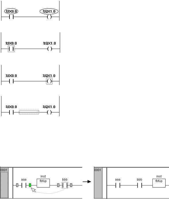
'Extras' 'Negate' in LD
Symbol:  Shortcut: <Ctrl>+<N>
Use this command to negate a contact, a coil, a jump or return instruction, or an input or output of EN POUs at the present cursor position.
Between the parentheses of the coil or between the straight lines of the contact, a slash will appear ((/) or |/|). If there are jumps, returns, or inputs or outputs of EN POUs, a small circle will appear at the connection, just as in the FBD editor.
5-32 |
CoDeSys V2.3 |