

5 - Editors in CoDeSys
5.3.3The Editor for Structured Text...
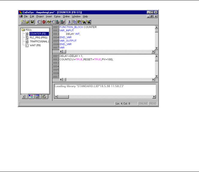
This is how a POU written in ST appears under the corresponding CoDeSys editor:
All editors for POUs consist of a declaration part and a body. These are separated by a screen divider.
The editor for Structured Text is a text editor with the usual capabilities of Windows text editors. The most important commands are found in the context menu (right mouse button or <Ctrl>+<F10>).
For information about the language, see Chapter 2.2.2, 'Structured Text (ST).
5.4The Graphic Editors...
5.4.1Working in graphic editors
The editors of the graphically oriented languages, sequential function chart SFC, ladder diagram LD and function block diagram FBD and of free graphic function block diagrams have many points in common. In the following paragraphs these features will be summarized; the specific descriptions of LD, FBD an CFC, as well as the Sequential Function Chart language SFC follow in separate sections. The implementation in the graphics editors is supported by syntax coloring.
Zoom
Objects such as POUs, actions, transitions etc. in the languages SFC, LD, FBD, CFC and in visualizations can be enlarged or reduced in size with a zoom function. All elements of the window contents of the implementation part are affected; the declaration part remains unchanged.
In standard form, every object is displayed with the zoom level 100%. The zoom level that is set is saved as an object property in the project.
The printing of project documentation always occurs at the 100% display level!
The zoom level can be set through a selection list in the toolbar. Values between 25% and 400% can be selected; individual values between 10% and 500% can be entered manually.
CoDeSys V2.3 |
5-21 |

The Graphic Editors...
The selection of a zoom level is only available if the cursor rests on an object created in a graphical language or a visualization object.
Even with the object zoomed, cursor positions in the editors can be further selected and even reached with the arrow keys. Text size is governed by the zoom factor and the font size that is set.
The execution of all editor menu features (e.g. inserting a box) as a function of cursor position is available at all zoom levels, taking the same into account.
In Online mode, each object is displayed according to the zoom level that has been set; Online functionality is available without restriction.
When the IntelliMouse is used, an object can be enlarged/reduced by pressing the <CTRL> key and at the same time turning the wheel forward or backwards.
Network
In the LD and FBD editors, the program is arranged in a list of networks. Each network is designated on the left side by a serial network number and has a structure consisting of either a logical or an arithmetic expression, a program, function or function block call, and a jump or a return instruction.
Label
Each network has a label that can optionally be left empty. This label is edited by clicking the first line of the network, directly next to the network number. Now you can enter a label, followed by a colon.
Network Comments, Networks with Linebreaks, 'Extras' 'Options'
Every network can be supplied with a multi-lined comment. In the dialog 'Function Block and Ladder Diagram Options', which can be opened by executing the command 'Extras' 'Options', you can do the settings concerning comments and linebreaks:
In the maximum comment size field you can enter the maximum number of lines to be made available for a network comment (The default value here is 4.) In the field minimum comment size you can enter the number of lines that generally should be reserved for . If, for example, the number 2 is entered, then, at the start of each network there will be two empty lines after the label line. The default value here is 0, which has the advantage of allowing more networks to fit in the screen area.
If the minimal comment size is greater than 0, then in order to enter a comment you simply click in the comment line and then enter the comment. Otherwise you first must select the network to which a comment is to be entered, and use 'Insert' 'Comment' to insert a comment line. In contrast to the program text, comments are displayed in grey.
In the Ladder editor you can also assign an individual comment to each contact or coil. For this activate the option Comments per Contact and insert in the edit field Lines for variable comment the number of lines which should be reserved and displayed for the comment. If this setting is done, a comment field will be displayed in the editor above each contact and coil where you can insert text.
If the option Comments per Contact is activated, then in the Ladder editor also the number of lines (Lines for variable text :) can be defined which should be used for the variable name of the contact resp. coil. This is used to display even long names completely by breaking them into several lines.
In the Ladder editor it is possible to force linebreaks in the networks as soon as the network length would exceed the given window size and some of the elements would not be visible. For this activate the option Networks with Linebreaks.
'Insert' 'Network (after)' or 'Insert' 'Network (before)' Shortcut: <Shift>+<T> (Network after)
In order to insert a new network in the FBD or the LD editor, select the 'Insert' 'Network (after)' or the 'Insert' 'Network (before)' command, depending on whether you want to insert the new network before or after the present network. The present network can be changed by clicking the network number. You will recognize it in the dotted rectangle under the number. With the <Shift key> and a mouse click you can select from the entire area of networks, from the present one to the one clicked.
5-22 |
CoDeSys V2.3 |
5 - Editors in CoDeSys
The network editors in the online mode
In the FBD and the LD editors you can only set breakpoints for networks. The network number field of a network for which a breakpoint has been set, is displayed in blue. The processing then stops in front of the network, where the breakpoint is located. In this case, the network number field is displayed in red. With single step processing (steps), you can jump from network to network.
All values are monitored upon entering and exiting network POUs (Program Organization Units).
The following should be noted when monitoring expressions or Bit-addressed variables: In expressions, e.g. a AND b, used as transition condition or function block input, the value of the whole expression is always displayed (a AND b is shown in blue or as :=TRUE, if a and b are TRUE). For Bit-addressed variables, the bit value that is addressed is always monitored (e.g. a.3 is displayed in blue or with „:=TRUE, if a has the value 4)
The flow control is run with the 'Online' 'Flow control' command. Using the flow control, you can view the present values that are being carried in the networks over the connecting lines. If the connecting lines do not carry Boolean values, then the value will be displayed in a specially inserted field. The monitor fields for variables that are not used (e.g. in the function SEL) are displayed in a shade of grey. If the lines carry Boolean values, then they will be shaded blue, in the event that they carry TRUE. Therefore, you can accompany the flow of information while the PLC is running.
If you place the mouse pointer briefly above a variable, then the type, the address and the comment about the variable will be displayed in a Tooltip.
5.4.2The Function Block Diagram Editor...
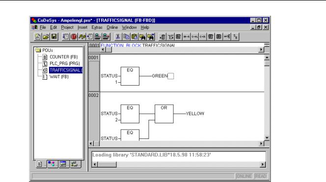
This is how a POU written in the FBD under the corresponding CoDeSys editor looks:
The Function Block Diagram editor is a graphic editor. It works with a list of networks, in which every network contains a structure that displays, respectively, a logical or an arithmetical expression, the calling up of a function block, a function, a program, a jump, or a return instruction. The most important commands are found in the context menu (right mouse button or <Ctrl>+<F10>).
Regard the possibility to switch the display of a FUP-POU between FUPand KOP editor, in offline mode as well as in online mode.
CoDeSys V2.3 |
5-23 |
The Graphic Editors...
Cursor positions in FBD
Every text is a possible cursor position. The selected text is on a blue background and can now be changed.
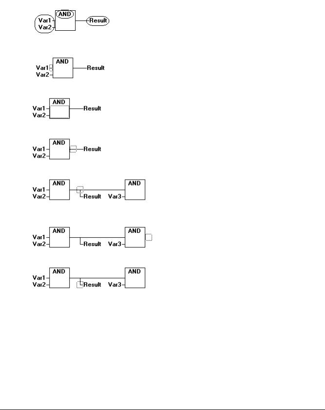
You can also recognize the present cursor position by a dotted rectangle. The following is a list of all possible cursor positions with an example:
1)Every text field (possible cursor positions framed in black):
2)Every input:
3)Every operator, function, or function block:
4)Outputs, if an assignment or a jump comes afterward:
5)The lined cross above an assignment, a jump, or a return instruction:
6)Behind the outermost object on the right of every network ("last cursor position," the same cursor position that was used to select a network):
7)The lined cross directly in front of an assignment:
How to set the cursor in FBD
The cursor can be set at a certain position by clicking the mouse, or with the help of the keyboard.
Using the arrow keys, you can jump to the nearest cursor position in the selected direction at any time. All cursor positions, including the text fields, can be accessed this way. If the last cursor position is selected, then the <up> or <down> arrow keys can be used to select the last cursor position of the previous or subsequent network.
An empty network contains only three question marks "???". By clicking behind these, the last cursor position is selected.
5-24 |
CoDeSys V2.3 |
5 - Editors in CoDeSys
'Insert' 'Assign' in FBD
Symbol:  Shortcut: <Ctrl>+<A>
This command inserts an assignment.
Depending on the selected position (see 'Cursor positions in FBD'), insertion takes place directly in front of the selected input (Cursor Position 2), directly after the selected output (Cursor Position 4) or at the end of the network (Cursor Position 6).
For an inserted assignment, a selection can be made accompanying the entered text "???", and the assignment can be replaced by the variable that is to be assigned. For this you can also use the Input Assistant.
In order to insert an additional assignment to an existing assignment, use the 'Insert' 'Output' command.
'Insert' 'Jump' in FBD
Symbol:  Shortcut: <Ctrl>+<L>
This command inserts a jump.
Depending on the selected position (see 'Cursor positions in FBD'), insertion takes place directly in front of the selected input (Cursor Position 2), directly after the selected output (Cursor Position 4) or at the end of the network (Cursor Position 6).
For an inserted jump, a selection can be made accompanying the entered text "???", and the jump can be replaced by the label to which it is to be assigned.
'Insert' 'Return' in FBD
Symbol:  Shortcut: <Ctrl>+<R>
This command inserts a RETURN instruction.
Depending on the selected position (see 'Cursor positions in FBD'), insertion takes place directly in front of the selected input (Cursor Position 2),directly after the selected output (Cursor Position 4), directly before the selected line cross (Cursor Position 5), or at the end of the network (Cursor Position 6)
'Insert' 'Box' in FBD
Symbol:  Shortcut: <Ctrl>+<B>
With this command, operators, functions, function blocks and programs can be inserted. First of all, it is always inserted an "AND" operator. This can be converted by Selection and Overwrite of the type text („AND") into every other operator, into every function, into every function block and every program. You can select the desired POU by using Input Assistant (<F2>). If the new selected block has another minimum number of inputs, these will be attached. If the new block has a smaller highest number of inputs, the last inputs will be deleted.
In functions and function blocks, the formal names of the inand outputs are displayed.
In function blocks there exists an editable instance field above the box. If another function block that is not known is called by changing the type text, an operator box with two inputs and the given type is displayed. If the instance field is selected, Input Assistant can be obtained via <F2> with the categories for variable selection.
The newest POU is inserted at the selected position:
•If an input is selected (Cursor Position 2), then the POU is inserted in front of this input. The first input of this POU is linked to the branch on the left of the selected input. The output of the new POU is linked to the selected input.
CoDeSys V2.3 |
5-25 |

The Graphic Editors...
•If an output is selected (Cursor Position 4), then the POU is inserted after this output. The first input of the POU is connected with the selected output. The output of the new POU is linked to the branch with which the selected output was linked.
•If a POU, a function, or a function block is selected (Cursor Position 3), then the old element will be replaced by the new POU.
•As far as possible, the branches will be connected the same way as they were before the replacement. If the old element had more inputs than the new one, then the unattachable branches will be deleted. The same holds true for the outputs.
•If a jump or a return is selected, then the POU will be inserted before this jump or return. The first input of the POU is connected with the branch to the left of the selected element. The output of the POU is linked to the branch to the right of the selected element.
•If the last cursor position of a network is selected (Cursor Position 6), then the POU will be inserted following the last element. The first input of the POU is linked to the branch to the left of the selected position.
All POU inputs that could not be linked will receive the text "???". This text must be clicked and changed into the desired constant or variable.
If there is a branch to the right of an inserted POU, then the branch will be assigned to the first POU output. Otherwise the outputs remain unassigned.
'Insert' 'Input'
Symbol:  Shortcut: <Ctrl>+<U>
This command inserts an operator input. With many operators, the number of inputs may vary. (For example, ADD can have 2 or more inputs.)
In order to extend such an operator by an input, you need to select the input in front of which you wish to insert an additional input (Cursor Position 1); or you must select the operator itself (Cursor Position 3), if a lowest input is to be inserted (see 'Cursor positions in FBD').
The inserted input is allocated with the text "???". This text must be clicked and changed into the desired constant or variable. For this you can also use the Input Assistant.
'Insert' 'Output'
Symbol: 
This command inserts an additional assignment into an existing assignment. This capability serves the placement of so-called assignment combs; i.e., the assignment of the value presently located at the line to several variables.
If you select the lined cross above an assignment (Cursor Position 5) (see 'Cursor positions in FBD') or the output directly in front of it (Cursor Position 4), then there will be another assignment inserted after the ones already there.
If the line cross directly in front of an assignment is selected (Cursor Position 4), then another assignment will be inserted in front of this one.
The inserted output is allocated with the text "???". This text must be clicked and changed into the desired variable. For this you can also use the Input Assistant.
'Extras' 'Negate
Symbol:  Shortcut: <Ctrl>+<N>
With this command you can negate the inputs, outputs, jumps, or RETURN instructions. The symbol for the negation is a small circle at a connection.
If an input is selected (Cursor Position 2) (see 'Cursor positions in FBD'), then this input will be negated.
5-26 |
CoDeSys V2.3 |
5 - Editors in CoDeSys
If an output is selected (Cursor Position 4), then this output will be negated.
If a jump or a return is marked, then the input of this jump or return will be negated.
A negation can be canceled through renewed negation.
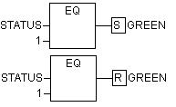
'Extras' 'Set/Reset'
Symbol: 
With this command you can define outputs as Set or Reset Outputs. A grid with Set Output is displayed with [S], and a grid with Reset Output is displayed with [R].
Set/Reset Outputs in FBD
An Output Set is set to TRUE, if the grid belonging to it returns TRUE. The output now maintains this value, even if the grid jumps back to FALSE.
An Output Reset is set to FALSE, if the grid belonging to it returns FALSE. The output maintains its value, even if the grid jumps back to FALSE.
With multiple executions of the command, the output will alternate between set, reset, and normal output.
'Extras' 'View'
Using this command for a POU created in the FBD-Editor you can choose, whether it should be displayed in the LD- (ladder logic) or in the FBD-Editor (Function block diagram). This is possible in offline as well as in online mode.
Open instance
This command corresponds to the 'Project' 'Open instance' command.
It is available in the context menu (<F2>) or in the 'Extras' menu, if the cursor is positioned on the name of a function block in a text editor or if the function block box is selected in a graphic editor.
Cutting, Copying, Pasting, and Deleting in FBD
The commands used to 'Cut', 'Copy', 'Paste', and 'Delete' are found under the 'Edit' menu item.
If a line cross is selected(Cursor Position 5) (see 'Cursor positions in FBD'), then the assignments, jumps, or RETURNS located below the crossed line will be cut, deleted, or copied.
If a POU is selected (Cursor Position 3), then the selected object itself, will be cut, deleted, or copied, along with all of the branches dependent on the inputs, with the exception of the first (highest position) branch.
Otherwise, the entire branch located in front of the cursor position will be cut, deleted, or copied.
After copying or cutting, the deleted or copied part is located on the clipboard and can now be pasted, as desired.
In order to do so, you must first select the pasting point. Valid pasting points include inputs and outputs.
If a POU has been loaded onto the clipboard (As a reminder: in this case all connected branches except the first are located together on the clipboard), the first input is connected with the branch before the pasting point.
CoDeSys V2.3 |
5-27 |