

8 СЕМЕСТР / АСУ ЭТО / Wago-IO-PRO CAA 2.3.8.5 (5.10.2007) / WAGO manuals / 750-833 / m083300e
.pdfFieldbus coupler / controller |
• 87 |
Fieldbus Controller 750-833 |
|
|
|
3.2.5Configuration
The configuration of the node is performed in accordance with the physical requirements of the fieldbus controllers and I/O modules.
The fieldbus controller or the process data channel is to be configured on the first slot.
The other slots are configured in accordance with the physical requirements of the I/O modules, whereby only I/O modules with process data are relevant. The supply modules without diagnosis, the supply modules without diagnosis, the bus internal system supply module and the termination module are to be ignored during configuration, as they do not provide any process data.
2 or 3 modules per I/O module are entered in the hardware catalogue. The modules appear as
750-xyz ..., e.g. 750-400 2 DI/24 V DC/3.0 ms. and
PFC 750-xyz ..., e.g.. PFC 750-400 2 DI/24 V DC/3.0 ms.
The identification PFC 750-xyz ... states that the module concerned is exclusively processed by the internal control application. Its process data is not transmitted via the PROFIBUS-DP to the master or to the higher ranking controls.
Alos the entry *750-xyz .... is listed for all binary modules. When using this identification the controller adds the binary information of the current module in a byte previously opened with 750-xyz .... The use of a „*“ module is only permitted when the number of channels is less or identical to the remaining bits in the previously opened byte. The binary I/O modules combined in a byte may be at different locations, i.e. binary I/O modules of a different signal type or byte orientated I/O modules can be connected between.
In order to configure the scope of the connected peripheries individually and independent of the control program, it is possible to parameter the I/O modules in the configuration table as „not plug fitted“. In this manner the process data still on the PROFIBUS DP can be filtered for the individual module and not transmitted to the periphery or read by it.
With the 750-833, after configuration of the connected periphery, the memory area is configured due to the variable arrangement of the fieldbus variables. For this the identification
1 byte PFC outputs, 2 byte PFC outputs to 64 byte PFC outputs
is available for the input image as well as
1 byte PFC inputs, 2 byte PFC inputs to 64 byte PFC inputs
for the output image.
By optionally combining the existing modules it is possible to project the required length on the fieldbus variables for PROFIBUS-DP.
WAGO-I/O-SYSTEM 750 |
D R A F T |
PROFIBUS |
2001-02-27 |

88 • Fieldbus coupler / controller
Fieldbus Controller 750-833
3.2.5.1GSD files
Under PROFIBUS DP the power features of the devices are defined by the manufacturer in the form of a GSD file (device master data) and made available to the user.
Structure, content and coding of this device master data are standardised so that projecting with any DP slaves with projecting data from various manufacturers is possible.
Further information
i The PNO provides information about the GSD files of all listed manufacturers.
GSD and symbol files for the configuration of the I/O modules are available under the order number 750-910 on disk or from the WAGO INTERNET page.
http://www.wago.com
GSD file for I/O module 750-833 |
WAGOB756.GSD |
|
|
The GSD file is read by the configuration software and the corresponding settings transferred. For the necessary entries and handling steps please refer to the software user manuals.
D R A F T |
WAGO-I/O-SYSTEM 750 |
2001-02-27 |
PROFIBUS |

Fieldbus coupler / controller |
• 89 |
Fieldbus Controller 750-833 |
|
|
|
3.2.5.2Identification bytes
The identification bytes contain information about the structure and the scope of the inputs and outputs of the devices. For projecting each I/O module or each channel is allocated an identification (module).
Bit |
|
|
|
|
|
|
|
Meaning |
7 |
6 |
5 |
4 |
3 |
2 |
1 |
0 |
|
|
|
|
|
|
|
|
|
Data length |
|
|
|
|
0 |
0 |
0 |
0 |
1 byte or word |
|
|
|
|
0 |
0 |
0 |
1 |
2 bytes or words |
|
|
|
|
0 |
0 |
1 |
0 |
3 bytes or words |
|
|
|
|
... |
... |
... |
... |
... |
|
|
|
|
1 |
1 |
1 |
1 |
16 bytes or 16 words |
|
|
|
|
|
|
|
|
Input and output |
|
|
0 |
0 |
|
|
|
|
Spec. identification formats |
|
|
0 |
1 |
|
|
|
|
Input |
|
|
1 |
0 |
|
|
|
|
Output |
|
|
1 |
1 |
|
|
|
|
Input and output |
|
|
|
|
|
|
|
|
Format |
|
0 |
|
|
|
|
|
|
0 = Byte structure |
|
1 |
|
|
|
|
|
|
1 = Word structure |
|
|
|
|
|
|
|
|
Consistency about |
0 |
|
|
|
|
|
|
|
Byte or word |
1 |
|
|
|
|
|
|
|
Total length |
For the special identification byte (Bit 4 and 5 = 00) is defined:
Bit |
|
|
|
|
|
|
|
Meaning |
7 |
6 |
5 |
4 |
3 |
2 |
1 |
0 |
|
|
|
|
|
|
|
|
|
Length of the manufacturer specific data |
|
|
|
|
0 |
0 |
0 |
0 |
0 = no manufacturer specific data |
|
|
|
|
0 |
0 |
0 |
1 |
|
|
|
|
|
... |
... |
... |
... |
1 ... 14 = Length of the manufacturer specific data |
|
|
|
|
1 |
1 |
1 |
0 |
|
|
|
|
|
1 |
1 |
1 |
1 |
15 = no manufacturer specific data follows |
|
|
|
|
|
|
|
|
Input and output |
|
|
0 |
0 |
|
|
|
|
Spec. identification formats |
|
|
|
|
|
|
|
|
Input and output |
0 |
0 |
|
|
|
|
|
|
unassigned slot |
0 |
1 |
|
|
|
|
|
|
a length byte for inputs follows |
1 |
0 |
|
|
|
|
|
|
a length byte for outputs follows |
1 |
1 |
|
|
|
|
|
|
a length byte for inputs and outputs follows |
Structure of the length byte:
Bit |
|
|
|
|
|
|
|
Meaning |
7 |
6 |
5 |
4 |
3 |
2 |
1 |
0 |
|
|
|
|
|
|
|
|
|
Data length |
|
|
0 |
0 |
0 |
0 |
1 |
0 |
1 byte or word |
|
|
... |
... |
... |
... |
... |
... |
... |
|
|
1 |
1 |
1 |
1 |
1 |
1 |
63 bytes or 63 words |
|
|
|
|
|
|
|
|
Format |
|
0 |
|
|
|
|
|
|
0 = Byte structur |
|
1 |
|
|
|
|
|
|
1 = Word structur |
|
|
|
|
|
|
|
|
Consistency about |
0 |
|
|
|
|
|
|
|
Byte or word |
1 |
|
|
|
|
|
|
|
Total length |
WAGO-I/O-SYSTEM 750 |
D R A F T |
PROFIBUS |
2001-02-27 |

90 • Fieldbus coupler / controller
Fieldbus Controller 750-833
This information is saved in the GSD file. For projecting the I/O module is selected in accordance with the article number using the configuration software contained in the hardware catalogue of the I/O module.
Module |
|
|
Ident. |
Module |
Ident. |
Module |
|
Ident. |
750-833 No process data channel |
0x00 |
|
|
|
|
|
||
750-833 2 byte process data |
0xB1 |
|
|
|
|
|
||
channel |
|
|
|
|
|
|
|
|
750-400 2 |
DI/24 V DC/3.0 ms |
0x10 |
*750-400 2 DI/24 V DC/3.0 ms |
0x00 |
PFC 750-400 2 DI/24 V DC/3.0 ms |
0x00 |
||
750-401 2 |
DI/24 V DC/0.2 ms |
0x10 |
*750-401 2 DI/24 V DC/0.2 ms |
0x00 |
PFC 750-401 2 DI/24 V DC/0.2 ms |
0x00 |
||
750-402 4 |
DI/24 V DC/3.0 ms |
0x10 |
*750-402 4 DI/24 V DC/3.0 ms |
0x00 |
PFC 750-402 4 DI/24 V DC/3.0 ms |
0x00 |
||
750-403 4 |
DI/24 V DC/0.2 ms |
0x10 |
*750-403 4 DI/24 V DC/0.2 ms |
0x00 |
PFC 750-403 4 DI/24 V DC/0.2 ms |
0x00 |
||
750-404 Counter Module |
0xF2 |
PFC 750-404 Counter Module |
0x00 |
|
|
|
||
750-405 2 |
DI/230 V AC/10 ms |
0x10 |
*750-405 2 DI/230 V AC/10 ms |
0x00 |
PFC 750-405 2 DI/230 V AC/10 ms |
0x00 |
||
750-406 2 |
DI/120 V AC/10 ms |
0x10 |
*750-406 2 DI/120 V AC/10 ms |
0x00 |
PFC 750-406 2 DI/120 V AC/10 ms |
0x00 |
||
750-408 4 |
DI/24 V DC/3.0 ms |
0x10 |
*750-408 4 DI/24 V DC/3.0 ms |
0x00 |
PFC 750-408 4 DI/24 V DC/3.0 ms |
0x00 |
||
750-409 4 |
DI/24 V DC/0.2 ms |
0x10 |
*750-409 4 DI/24 V DC/0.2 ms |
0x00 |
PFC 750-409 4 DI/24 V DC/0.2 ms |
0x00 |
||
750-410 2 |
DI/24 V DC/3.0 ms |
0x10 |
*750-410 2 DI/24 V DC/3.0 ms |
0x00 |
PFC 750-410 2 DI/24 V DC/3.0 ms |
0x00 |
||
750-411 2 |
DI/24 V DC/0.2 ms |
0x10 |
*750-411 2 DI/24 V DC/0.2 ms |
0x00 |
PFC 750-411 2 DI/24 V DC/0.2 ms |
0x00 |
||
750-412 2 |
DI/48 V DC/3.0 ms |
0x10 |
*750-412 2 DI/48 V DC/3.0 ms |
0x00 |
PFC 750-412 2 DI/48 V DC/3.0 ms |
0x00 |
||
750-413 2 |
DI/48 V DC/0.2 ms |
0x10 |
*750-413 2 DI/48 V DC/0.2 ms |
0x00 |
PFC 750-413 2 DI/48 V DC/0.2 ms |
0x00 |
||
750-414 4 |
DI/5 V DC/0.2 ms |
0x10 |
*750-414 4 DI/5 V DC/0.2 ms |
0x00 |
PFC 750-414 4 DI/5 V DC/0.2 ms |
0x00 |
||
750-415 4 DI/24 V AC/DC/20 ms |
0x10 |
*750-415 4 DI/24 V AC/DC/20 ms |
0x00 |
PFC 750-415 4 DI/24 V |
0x00 |
|||
|
|
|
|
|
|
AC/DC/20ms |
|
|
750-418 2 DI/24 V DC DIA ACK |
0x30 |
*750-418 2 DI/24 V DC DIA ACK |
0x00 |
PFC 750-418 2 DI/24 V DC DIA |
0x00 |
|||
|
|
|
|
|
|
ACK |
|
|
750-419 2 DI/24 V DC DIA |
0x10 |
*750-419 2 DI/24 V DC DIA |
0x00 |
PFC 750-419 2 DI/24 V DC DIA |
0x00 |
|||
750-423 4 DI/24 V AC/DC/50 ms |
0x10 |
*750-423 4 DI/24 V AC/DC/50 ms |
0x00 |
PFC 750-423 4 DI/24 V |
0x00 |
|||
|
|
|
|
|
|
AC/DC/50ms |
|
|
750-424 2 DI/24 V DC DIA |
0x10 |
*750-424 2 DI/24 V DC DIA |
0x00 |
PFC 750-424 2 DI/24 V DC DIA |
0x00 |
|||
750-452 |
2 |
AI/0-20 mA/diff. |
0x51 |
|
|
PFC 750-452 |
2 AI/0-20 mA/diff. |
0x00 |
750-454 |
2 |
AI/4-20 mA/diff. |
0x51 |
|
|
PFC 750-454 |
2 AI/4-20 mA/diff. |
0x00 |
750-456 |
2 |
AI/±10 V/diff. |
0x51 |
|
|
PFC 750-456 |
2 AI/±10 V/diff. |
0x00 |
750-461 2 |
AI/RTD |
0x51 |
|
|
PFC 750-461 2 AI/RTD |
0x00 |
||
750-462 2 |
AI/TC |
0x51 |
|
|
PFC 750-462 2 AI/TC |
0x00 |
||
750-465 2 |
AI/0-20 mA/SE |
0x51 |
|
|
PFC 750-465 2 AI/0-20 mA/SE |
0x00 |
||
750-466 2 |
AI/4-20 mA/SE |
0x51 |
|
|
PFC 750-466 2 AI/4-20 mA/SE |
0x00 |
||
750-467 2 |
AI/0-10 V/SE |
0x51 |
|
|
PFC 750-467 2 AI/0-10 V/SE |
0x00 |
||
750-468 4 |
AI/0-10 V/SE |
0x53 |
|
|
PFC 750-468 4 AI/0-10 V/SE |
0x00 |
||
750-469 2 AI/TC/OCM |
0x51 |
|
|
PFC 750-469 2 AI/TC/OCM |
0x00 |
|||
750-472 2 |
AI/0-20 mA/OVLP |
0x51 |
|
|
PFC 750-472 2 AI/0-20 mA/OVLP |
0x00 |
||
750-474 2 |
AI/4-20 mA/OVLP |
0x51 |
|
|
PFC 750-474 2 AI/4-20 mA/OVLP |
0x00 |
||
750-476 2 |
AI/±10 V |
0x51 |
|
|
PFC 750-476 2 AI/±10 V |
0x00 |
||
750-478 2 |
AI/0-10 V |
0x51 |
|
|
PFC 750-478 2 AI/0-10 V |
0x00 |
||
750-501 2 DO/24 V DC/0.5 A |
0x20 |
*750-501 2 DO/24 V DC/0.5 A |
0x00 |
PFC 750-501 2 DO/24 V DC/0.5 A |
0x00 |
|||
750-502 2 DO/24 V DC/2.0 A |
0x20 |
*750-502 2 DO/24 V DC/2.0 A |
0x00 |
PFC 750-502 2 DO/24 V DC/2.0 A |
0x00 |
|||
750-504 4 DO/24 V DC/0.5 A |
0x20 |
*750-504 4 DO/24 V DC/0.5 A |
0x00 |
PFC 750-504 4 DO/24 V DC/0.5 A |
0x00 |
|||
750-506 2 DO/24 V DC/0.5 A DIA |
0x20 |
*750-506 2 DO/24 V DC/0.5 A DIA |
0x00 |
PFC 750-506 2 DO/24 V DC/0.5 A |
0x00 |
|||
750-507 2 DO/24 V DC/2.0 A DIA |
0x20 |
*750-507 2 DO/24 V DC/2.0 A DIA |
0x00 |
PFC 750-507 2 DO/24 V DC/2.0 A |
0x00 |
|||
750-509 2 DO/230 V AC/0.3 A |
0x20 |
*750-509 2 DO/230 V AC/0.3 A |
0x00 |
PFC 750-509 2 DO/230 V AC/0.3 A |
0x00 |
|||
750-511 2 DO 24 V DC/PWM |
0xF2 |
|
|
PFC 750-511 2 DO 24 V DC/PWM |
0x00 |
|||
750-512 2 DO Relay/250 V AC |
0x20 |
*750-512 2 DO Relay/250 V AC |
0x00 |
PFC 750-512 2 DO Relay/250 V AC |
0x00 |
|||
750-513 2 DO Relay/250 V AC |
0x20 |
*750-513 2 DO Relay/250 V AC |
0x00 |
PFC 750-513 2 DO Relay/250 V AC |
0x00 |
|||
750-514 2 DO Relay/125 V AC |
0x20 |
*750-514 2 DO Relay/125 V AC |
0x00 |
PFC 750-514 2 DO Relay/125 V AC |
0x00 |
|||
750-516 4 DO/24 V DC/0.5 A |
0x20 |
*750-516 4 DO/24 V DC/0.5 A |
0x00 |
PFC 750-516 4 DO/24 V DC/0.5 A |
0x00 |
|||
750-517 2 |
DO Relay/230 V AC |
0x20 |
*750-517 2 DO Relay/230 V AC |
0x00 |
PFC 750-517 2 DO Relay/230 V AC |
0x00 |
||
750-519 4 DO/5 V DC/20 mA |
0x20 |
*750-519 4 DO/5 V DC/20 mA |
0x00 |
PFC 750-519 4 DO/5 V DC/20 mA |
0x00 |
|||
750-522 2 |
DO/230V AC/0.5 A |
0x20 |
*750-522 2 DO/230V AC/0.5 A |
0x00 |
PFC 750-522 2 DO/230V DC/0.5 A |
0x00 |
||
DIA |
|
|
|
DIA |
|
|
|
|
750-550 2 |
AO/0-10 V |
0x61 |
|
|
PFC 750-550 2 AO/0-10 V |
0x00 |
||
750-552 2 AO/0-20 mA |
0x61 |
|
|
PFC 750-552 2 AO/0-20 mA |
0x00 |
|||
750-554 2 AO/4-20 mA |
0x61 |
|
|
PFC 750-554 2 AO/4-20 mA |
0x00 |
|||
750-556 2 AO/±10 V |
0x61 |
|
|
PFC 750-556 2 AO/±10 V |
0x00 |
|||
750-610 P supply. 24 V DC/DIA |
0x00 |
|
|
|
|
|
||
750-611 P supply. 230 V AC/DIA |
0x00 |
|
|
|
|
|
||
750-630 |
SSI-Intf. Standard |
0x95 |
750-630 SSI-Intf. alternative |
0x93 |
PFC 750-630 |
SS intf. |
0x00 |
|
750-631 |
Encoder intf. |
0xB5 |
PFC 750-631 Encoder intf. |
0x00 |
|
|
|
|
750-650 RS232C-Intf. 5 Byte |
0xB5 |
750-650 RS232C-Intf. 3 Byte |
0xB3 |
PFC 750-650 RS232C intf. |
0x00 |
|||
750-651 TTY-Intf. 5 Byte |
0xB5 |
750-651 TTY-Intf. 3 Byte |
0xB3 |
PFC 750-651 TTY-Intf. |
0x00 |
|||
750-653 |
RS485-Intf. 5 Byte |
0xB5 |
750-653 RS485 intf. 3 Byte |
0xB3 |
PFC 750-653 |
RS485intf. |
0x00 |
|
750-654 Data exch. module |
0xF1 |
|
|
PFC 750-654 Data exch. module |
0x00 |
|||
|
|
|
|
|
|
|||
1 Byte PFC-input |
0xA0 |
2 Byte PFC inputs |
0xA1 |
3 Byte PFC inputs |
0xA2 |
|||
4 Byte PFC inputs |
0xA3 |
5 Byte PFC inputs |
0xA4 |
6 Byte PFC inputs |
0xA5 |
|||
7 Byte PFC inputs |
0xA6 |
8 Byte PFC inputs |
0xA7 |
9 Byte PFC inputs |
0xA8 |
|||
D R A F T |
WAGO-I/O-SYSTEM 750 |
2001-02-27 |
PROFIBUS |

|
|
|
|
|
|
|
|
Fieldbus coupler / controller |
• 91 |
|||
|
|
|
|
|
|
|
|
Fieldbus Controller 750-833 |
|
|||
|
|
|
|
|
|
|
|
|
||||
|
|
|
|
|
|
|
|
|
||||
|
Module |
Ident. |
|
Module |
Ident. |
|
Module |
Ident. |
||||
|
10 |
Byte PFC inputs |
0xA9 |
|
11 |
Byte PFC inputs |
0xAA |
12 |
Byte PFC inputs |
0xAB |
||
|
13 |
Byte PFC inputs |
0xAC |
14 |
Byte PFC inputs |
0xAD |
15 |
Byte PFC inputs |
0xAE |
|||
|
16 |
Byte PFC inputs |
0xAF |
|
17 |
Byte PFC inputs |
0x80 |
, 0x90 |
18 |
Byte PFC inputs |
0x80 |
, 0x91 |
|
19 |
Byte PFC inputs |
0x80 |
, 0x92 |
20 |
Byte PFC inputs |
0x80 |
, 0x93 |
21 |
Byte PFC inputs |
0x80 |
, 0x94 |
|
22 |
Byte PFC inputs |
0x80 |
, 0x95 |
23 |
Byte PFC inputs |
0x80 |
, 0x96 |
24 |
Byte PFC inputs |
0x80 |
, 0x97 |
|
25 |
Byte PFC inputs |
0x80 |
, 0x98 |
26 |
Byte PFC inputs |
0x80 |
, 0x99 |
27 |
Byte PFC inputs |
0x80 |
, 0x9A |
|
28 |
Byte PFC inputs |
0x80 |
, 0x9B |
29 |
Byte PFC inputs |
0x80 |
, 0x9C |
30 |
Byte PFC inputs |
0x80 |
, 0x9D |
|
31 |
Byte PFC inputs |
0x80 |
, 0x9E |
32 byte PFC inputs |
0x80 |
, 0x9F |
33 |
Byte PFC inputs |
0x80 |
, 0xA0 |
|
|
34 |
Byte PFC inputs |
0x80 |
, 0xA1 |
35 |
Byte PFC inputs |
0x80 |
, 0xA2 |
36 |
Byte PFC inputs |
0x80 |
, 0xA3 |
|
37 |
Byte PFC inputs |
0x80 |
, 0xA4 |
38 |
Byte PFC inputs |
0x80 |
, 0xA5 |
39 |
Byte PFC inputs |
0x80 |
, 0xA6 |
|
40 |
Byte PFC inputs |
0x80 |
, 0xA7 |
41 |
Byte PFC inputs |
0x80 |
, 0xA8 |
42 |
Byte PFC inputs |
0x80 |
, 0xA9 |
|
43 |
Byte PFC inputs |
0x80 |
, 0xAA |
44 |
Byte PFC inputs |
0x80 |
, 0xAB |
45 |
Byte PFC inputs |
0x80 |
, 0xAC |
|
46 |
Byte PFC inputs |
0x80 |
, 0xAD |
47 |
Byte PFC inputs |
0x80 |
, 0xAE |
48 |
Byte PFC inputs |
0x80 |
, 0xAF |
|
49 |
Byte PFC inputs |
0x80 |
, 0xB0 |
50 |
Byte PFC inputs |
0x80 |
, 0xB1 |
51 |
Byte PFC inputs |
0x80 |
, 0xB2 |
|
52 |
Byte PFC inputs |
0x80 |
, 0xB3 |
53 |
Byte PFC inputs |
0x80 |
, 0xB4 |
54 |
Byte PFC inputs |
0x80 |
, 0xB5 |
|
55 |
Byte PFC inputs |
0x80 |
, 0xB6 |
56 |
Byte PFC inputs |
0x80 |
, 0xB7 |
57 |
Byte PFC inputs |
0x80 |
, 0xB8 |
|
58 |
Byte PFC inputs |
0x80 |
, 0xB9 |
59 |
Byte PFC inputs |
0x80 |
, 0xBA |
60 |
Byte PFC inputs |
0x80 |
, 0xBB |
|
61 |
Byte PFC inputs |
0x80 |
, 0xBC |
62 |
Byte PFC inputs |
0x80 |
, 0xBD |
63 |
Byte PFC inputs |
0x80 |
, 0xBE |
|
64 |
Byte PFC inputs |
0x80 |
, 0xBF |
|
|
|
|
|
|
|
|
|
|
|
|
|
|
|
|
|
|
|||
|
1 Byte PFC outputs |
0x90 |
|
2 Byte PFC outputs |
0x91 |
|
3 Byte PFC outputs |
0x92 |
|
|||
|
4 Byte PFC outputs |
0x93 |
|
5 Byte PFC outputs |
0x94 |
|
6 Byte PFC outputs |
0x95 |
|
|||
|
7 Byte PFC outputs |
0x96 |
|
8 Byte PFC outputs |
0x97 |
|
9 Byte PFC outputs |
0x98 |
|
|||
|
10 |
Byte PFC outputs |
0x99 |
|
11 |
Byte PFC outputs |
0x9A |
|
12 |
Byte PFC outputs |
0x9B |
|
|
13 |
Byte PFC outputs |
0x9C |
|
14 |
Byte PFC outputs |
0x9D |
|
15 |
Byte PFC outputs |
0x9E |
|
|
16 |
Byte PFC outputs |
0x9F |
|
17 |
Byte PFC outputs |
0x40 |
, 0x90 |
18 |
Byte PFC outputs |
0x40 |
, 0x91 |
|
19 |
Byte PFC outputs |
0x40 |
, 0x92 |
20 |
Byte PFC outputs |
0x40 |
, 0x93 |
21 |
Byte PFC outputs |
0x40 |
, 0x94 |
|
22 |
Byte PFC outputs |
0x40 |
, 0x95 |
23 |
Byte PFC outputs |
0x40 |
, 0x96 |
24 |
Byte PFC outputs |
0x40 |
, 0x97 |
|
25 |
Byte PFC outputs |
0x40 |
, 0x98 |
26 |
Byte PFC outputs |
0x40 |
, 0x99 |
27 |
Byte PFC outputs |
0x40 |
, 0x9A |
|
28 |
Byte PFC outputs |
0x40 |
, 0x9B |
29 |
Byte PFC outputs |
0x40 |
, 0x9C |
30 |
Byte PFC outputs |
0x40 |
, 0x9D |
|
31 |
Byte PFC outputs |
0x40 |
, 0x9E |
32 |
Byte PFC outputs |
0x40 |
, 0x9F |
33 |
Byte PFC outputs |
0x40 |
, 0xA0 |
|
34 |
Byte PFC outputs |
0x40 |
, 0xA1 |
35 |
Byte PFC outputs |
0x40 |
, 0xA2 |
36 |
Byte PFC outputs |
0x40 |
, 0xA3 |
|
37 |
Byte PFC outputs |
0x40 |
, 0xA4 |
38 |
Byte PFC outputs |
0x40 |
, 0xA5 |
39 |
Byte PFC outputs |
0x40 |
, 0xA6 |
|
40 |
Byte PFC outputs |
0x40 |
, 0xA7 |
41 |
Byte PFC outputs |
0x40 |
, 0xA8 |
42 |
Byte PFC outputs |
0x40 |
, 0xA9 |
|
43 |
Byte PFC outputs |
0x40 |
, 0xAA |
44 |
Byte PFC outputs |
0x40 |
, 0xAB |
45 |
Byte PFC outputs |
0x40 |
, 0xAC |
|
46 |
Byte PFC outputs |
0x40 |
, 0xAD |
47 |
Byte PFC outputs |
0x40 |
, 0xAE |
48 |
Byte PFC outputs |
0x40 |
, 0xAF |
|
49 |
Byte PFC outputs |
0x40 |
, 0xB0 |
50 |
Byte PFC outputs |
0x40 |
, 0xB1 |
51 |
Byte PFC outputs |
0x40 |
, 0xB2 |
|
52 |
Byte PFC outputs |
0x40 |
, 0xB3 |
53 |
Byte PFC outputs |
0x40 |
, 0xB4 |
54 |
Byte PFC outputs |
0x40 |
, 0xB5 |
|
55 |
Byte PFC outputs |
0x40 |
, 0xB6 |
56 |
Byte PFC outputs |
0x40 |
, 0xB7 |
57 |
Byte PFC outputs |
0x40 |
, 0xB8 |
|
58 |
Byte PFC outputs |
0x40 |
, 0xB9 |
59 |
Byte PFC outputs |
0x40 |
, 0xBA |
60 |
Byte PFC outputs |
0x40 |
, 0xBB |
|
61 |
Byte PFC outputs |
0x40 |
, 0xBC |
62 |
Byte PFC outputs |
0x40 |
, 0xBD |
63 |
Byte PFC outputs |
0x40 |
, 0xBE |
|
64 |
Byte PFC outputs |
0x40 |
, 0xBF |
|
|
|
|
|
|
|
|
WAGO-I/O-SYSTEM 750 |
D R A F T |
PROFIBUS |
2001-02-27 |
92 • Fieldbus coupler / controller
Fieldbus Controller 750-833
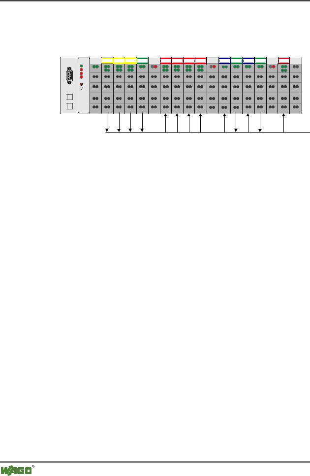
3.2.5.3Example
A fieldbus node with a controller and 17 I/O modules should make the arrangement clear.
1 |
2 |
3 |
4 |
5 |
6 |
7 |
8 |
9 |
10 |
11 |
12 |
13 |
14 |
15 |
16 |
17 |
DI DI |
DI DI |
DI DI |
AI AI |
DO DO DO DO DO DO DO DO |
AO AO |
AI AI |
AO AO AI AI |
DO DO |
750-333
402 |
402 |
402 |
452 |
602 |
504 |
504 |
504 |
504 |
602 |
550 |
452 |
550 |
452 |
602 |
504 |
600 |
Fig. 3-21: Example application
PROFIBUS
g012115x
No. |
I/O modules |
Modul |
PI Master * |
|
|
|
Identification |
|
|
|
|
Inputs |
Outputs |
|
|
|
|
||
1 |
Digital input |
750-402 4 DI/24 V DC/3.0 ms |
EB12.0 |
|
|
|
|
|
|
|
Digital input |
0x10 |
EB12.1 |
|
|
|
|
|
|
|
Digital input |
|
EB12.2 |
|
|
|
|
|
|
|
Digital input |
|
EB12.3 |
|
|
|
|
|
|
2 |
Digital input |
*750-402 4 DI/24 V DC/3.0 ms |
EB12.4 |
|
|
|
|
|
|
|
Digital input |
0x00 |
EB12.5 |
|
|
|
|
|
|
|
Digital input |
|
EB12.6 |
|
|
|
|
|
|
|
Digital input |
|
EB12.7 |
|
|
|
|
|
|
3 |
Digital input |
750-402 4 DI/24 V DC/3.0 ms |
EB13.0 |
|
|
|
|
|
|
|
Digital input |
0x10 |
EB13.1 |
|
|
|
|
|
|
|
Digital input |
|
EB13.2 |
|
|
|
|
|
|
|
Digital input |
|
EB13.3 |
|
|
|
|
|
|
4 |
Analog input |
750-452 2 AI/0-20 mA/diff. |
EW0 |
|
|
|
|
|
|
|
Analog input |
0x51 |
EW2 |
|
|
|
|
|
|
5 |
Potential supply |
Potential supply |
--- |
--- |
|
|
|
|
|
6 |
Digital output |
750-504 4 DO/24 V DC/0.5 A |
|
AB8.0 |
|
|
|
|
|
|
Digital output |
0x20 |
|
AB8.1 |
|
|
|
|
|
|
Digital output |
|
|
AB8.2 |
|
|
|
|
|
|
Digital output |
|
|
AB8.3 |
|
|
|
|
|
7 |
Digital output |
*750-504 4 DO/24 V DC/0.5 A |
|
AB8.4 |
|
|
|
|
|
|
Digital output |
0x00 |
|
AB8.5 |
|
|
|
|
|
|
Digital output |
|
|
AB8.6 |
|
|
|
|
|
|
Digital output |
|
|
AB8.7 |
|
|
|
|
|
D R A F T |
WAGO-I/O-SYSTEM 750 |
2001-02-27 |
PROFIBUS |

|
|
|
Fieldbus coupler / controller |
• 93 |
||||
|
|
|
Fieldbus Controller 750-833 |
|
|
|
||
|
|
|
|
|
|
|
|
|
|
|
|
|
|
|
|
|
|
|
8 |
Digital output |
750-504 4 DO/24 V DC/0.5 A |
|
AB9.0 |
|
|
|
|
|
|
|
|
|
|
|
|
|
|
Digital output |
0x20 |
|
AB9.1 |
|
|
|
|
|
|
|
|
|
|
|
|
|
|
Digital output |
|
|
AB9.2 |
|
|
|
|
|
|
|
|
|
|
|
|
|
|
Digital output |
|
|
AB9.3 |
|
|
|
|
|
|
|
|
|
|
|
|
|
9 |
Digital output |
*750-504 4 DO/24 V DC/0.5 A |
|
AB9.4 |
|
|
|
|
|
|
|
|
|
|
|
|
|
|
Digital output |
0x00 |
|
AB9.5 |
|
|
|
|
|
|
|
|
|
|
|
|
|
|
Digital output |
|
|
AB9.6 |
|
|
|
|
|
|
|
|
|
|
|
|
|
|
Digital output |
|
|
AB9.7 |
|
|
|
|
|
|
|
|
|
|
|
|
|
10 |
Potential supply |
Potential supply |
--- |
--- |
|
|
|
|
|
|
|
|
|
|
|
|
|
11 |
Analog output |
750-550 2 AO/0-10 V |
|
AW0 |
|
|
|
|
|
|
|
|
|
|
|
|
|
|
Analog output |
0x61 |
|
AW2 |
|
|
|
|
|
|
|
|
|
|
|
|
|
12 |
Analog input |
750-452 2 AI/0-20 mA/diff. |
EW4 |
|
|
|
|
|
|
|
|
|
|
|
|
|
|
|
Analog input |
0x51 |
EW6 |
|
|
|
|
|
|
|
|
|
|
|
|
|
|
13 |
Analog output |
750-550 2 AO/0-10 V |
|
AW4 |
|
|
|
|
|
|
|
|
|
|
|
|
|
|
Analog output |
0x61 |
|
AW6 |
|
|
|
|
|
|
|
|
|
|
|
|
|
14 |
Analog input |
750-452 2 AI/0-20 mA/diff. |
EW8 |
|
|
|
|
|
|
|
|
|
|
|
|
|
|
|
Analog input |
0x51 |
EW10 |
|
|
|
|
|
|
|
|
|
|
|
|
|
|
15 |
Potential supply |
Potential supply |
--- |
--- |
|
|
|
|
|
|
|
|
|
|
|
|
|
16 |
Digital output |
750-504 4 DO/24 V DC/0.5 A |
|
AB10.0 |
|
|
|
|
|
|
|
|
|
|
|
|
|
|
Digital output |
0x20 |
|
AB10.1 |
|
|
|
|
|
|
|
|
|
|
|
|
|
|
Digital output |
|
|
AB10.2 |
|
|
|
|
|
|
|
|
|
|
|
|
|
|
Digital output |
|
|
AB10.3 |
|
|
|
|
|
|
|
|
|
|
|
|
|
17 |
End module |
End module |
--- |
--- |
|
|
|
* The master addresses listed in the table correspond to the allocation of the process data given in the master configuration.
WAGO-I/O-SYSTEM 750 |
D R A F T |
PROFIBUS |
2001-02-27 |

94 • Fieldbus coupler / controller
Fieldbus Controller 750-833
3.2.6Parameterisation of the controllers
Before a data exchange can be performed between master and slave, a parameterisation is required in addition to configuration.
The extended parameters (Extended User_Prm_Data) are provided via the GSD files as selectable text in the configuration programs.
Description |
Value |
Meaning |
Restart the internal bus after a |
|
Restart of the terminal bus following a fault, |
fault |
POWER ON RESET*) |
such as, for example, no termination module |
|
following an interruption of the supply |
|
|
AUTORESET |
immediately after overcoming the internal bus |
|
|
fault |
I/O module diagnosis |
|
The diagnosis information of all I/O modules |
|
|
with a diagnosis capability, for which the |
|
released*) |
diagnosis is released are |
|
transferred to PROFIBUS-DP master, |
|
|
locked |
not transferred to PROFIBUS-DP master |
Process value display |
|
Word or double word oriented process data, is |
|
|
transferred to PROFIBUS-DP master in: |
|
INTEL |
„Little Endian Format“ |
|
MOTOROLA*) |
„Big Endian Format“ |
Behaviour in case of a |
|
In the case of a malfunction of the |
PROFIBUS DP fault |
|
PROFIBUS DP communication the status of the |
|
|
connected output periphery can be influenced in |
|
|
various ways: |
|
Stop internal bus transmis- |
The process data exchange on the internal bus is |
|
sion |
stopped, all outputs drop out after a module |
|
|
specific monitoring time of 100 ms |
|
Set output image to zero |
all outputs are immediately reset |
|
Freeze output image |
all outputs maintain the last status before the |
|
Write substitute value*) |
malfunction |
|
all outputs switch a parameterisable substitute |
|
|
|
value |
|
PFC fault strategy |
PFC takes over the control via the output image |
|
|
|
Reaction to an internal bus fault |
|
In the event of a malfunction of an internal |
|
|
communication between fieldbus controller and |
|
|
I/O modules, such as, for example no termina- |
|
|
tion module, |
|
Stop PROFIBUS data |
the data exchange with the PROFIBUS master |
|
exchange*) |
is stopped. |
|
Set input image to zero |
the input information is set to zero |
|
Freeze input image |
the input information prevailing before the fault |
|
|
is maintained |
|
*) Default settings |
|
D R A F T |
WAGO-I/O-SYSTEM 750 |
2001-02-27 |
PROFIBUS |

Fieldbus coupler / controller |
• 95 |
Fieldbus Controller 750-833 |
|
|
|
The complete data block encompasses 34 parameterised bytes. The first 10 bytes are laid down via the DP and DPV1 standard. The others receive manufacturer specific parameters.
Byte No. |
Bit No. |
Value |
Meaning |
|
Standard parameters |
|
|
|
|
0 |
0-7 |
|
Station status (see EN 50170) |
|
1 |
0-7 |
2-255 |
Watchdog factor 1 |
|
2 |
0-7 |
2-255 |
Watchdog factor 2 |
|
|
|
|
Watchdog: |
|
|
|
|
The response monitoring is the result of |
|
|
|
|
Watchdog_Factor_1 x Watchdog_Factor_2 x 10 ms (1 ms) |
|
3 |
0-7 |
11-255 |
Min TSDR, |
|
|
|
|
Earliest time in TBit after which the slave can reply |
|
4 |
0-7 |
183, 0xB7 |
Manufacturer Identification |
(high byte) |
5 |
0-7 |
86, 0x56 |
Manufacturer Identification |
(low byte) |
6 |
0-7 |
|
Group membership, |
|
|
|
|
Broad and multicast telegrams (SYNC, FREEZE) |
|
7 |
0-7 |
|
DPV1 status 1 (see EN 50170) |
|
8 |
0-7 |
|
DPV1 status 2 (see EN 50170) |
|
9 |
0-7 |
|
DPV1 status 3 (see EN 50170) |
|
Manufacturer parameters |
|
|
||
10 |
0-7 |
0 |
Table 0, register 0 LB, reserved |
|
11 |
0-7 |
0 |
Table 0, register 0 HB, reserved |
|
12 |
0-7 |
0 |
Table 0, register 1 LB, reserved |
|
13 |
0-7 |
0 |
Table 0, register 1 HB, reserved |
|
14 |
|
|
Table 0, register 2 LB |
|
|
0 |
0 |
Device diagnosis locked |
|
|
0 |
1*) |
Device diagnosis released |
|
|
1 |
0 |
Internal bus restart after fault: POWER-ON-RESET |
|
|
1 |
1*) |
Internal bus restart after fault: AUTORESET |
|
|
2-7 |
0 |
reserved |
|
15 |
0-7 |
0 |
Table 0, register 2 HB, reserved |
|
16 |
|
|
Table 0, register 3 LB |
|
|
0-2 |
'011' |
reserved |
|
|
3 |
0 |
Data format byte orientated I/O modules: INTEL |
|
|
3 |
1*) |
Data format byte orientated I/O modules: MOTOROLA |
|
|
4-7 |
'1100' |
reserved |
|
17 |
|
|
Table 0, register 3 HB |
|
|
0-2 |
'000' |
Reaction to fieldbus fault: |
|
|
|
- Stop internal bus transmission |
||
|
|
'001' |
- Set output image to zero |
|
|
|
'010' |
- Freeze output image |
|
|
|
'011' *) |
- Write substitute values |
|
|
|
'100' |
- PFC fault strategy |
|
|
|
'101' |
- Not possible |
|
|
|
'110' |
- Not possible |
|
|
|
'111' |
- Not possible |
|
|
3-5 |
'000' *) |
Reaction to internal bus fault: |
|
|
|
- Exit data exchange |
|
|
|
|
'001' |
- Set input image to zero |
|
|
|
'010' |
- Freeze input image |
|
|
|
'011' |
- Not possible |
|
|
|
'100' |
- Not possible |
|
|
|
'101' |
- Not possible |
|
|
|
'110' |
- Not possible |
|
|
|
'111' |
- Not possible |
|
|
6-7 |
'00' |
reserved |
|
18 |
0-7 |
'1100.0011' |
Table 0, register 4 LB, reserved |
|
19 |
0-7 |
'0111.1111' |
Table 0, register 4 HB, reserved |
|
20 |
0-7 |
'0000.0000' |
Table 100, register 0 LB, reserved |
|
21 |
0-7 |
'0000.0001' |
Table 100, register 0 HB, reserved |
|
22 |
0-7 |
'0000.0000' |
Table 100, register 1 LB, reserved |
|
23 |
0-7 |
'0000.0000' |
Table 100, register 1 HB, reserved |
|
24 |
0-7 |
'0000.0000' |
Table 100, register 2 LB, reserved |
|
25 |
0-7 |
'0000.0000' |
Table 100, register 2 HB, reserved |
|
WAGO-I/O-SYSTEM 750 |
D R A F T |
PROFIBUS |
2001-02-27 |

96 • Fieldbus coupler / controller
Fieldbus Controller 750-833
3.2.7Configuration of the process data channels
The process data channels serve the communication between the WAGO-I/O- PRO and the running time system of the fieldbus controller. If this channel is not required it can be projected with a process data length of zero
(750-833 No process data channel).
Module |
Identification |
Identification |
|
hex |
dec |
750-833 no process data channel |
0x00 |
0 |
750-833 2 byte process data channel |
0xB1 |
177 |
Note
Configure the module 750-833 2 byte process data channel or 750-833 No process data channel as 1st module.
D R A F T |
WAGO-I/O-SYSTEM 750 |
2001-02-27 |
PROFIBUS |