

Ceramic materials Carter Horton / fulltext 22 Sol Gell organic chemistry
.pdf22
Sols, Gels, and Organic Chemistry
CHAPTER PREVIEW
Extensive research and development in the past decade have resulted in increasing awareness of the importance of chemical synthesis, particularly using organic precursors, in the processing and fabrication of ceramics. The sol-gel process is one method that is used commercially in many applications, such as forming coatings on window glass. It is also used, as we have previously described, for forming powders and fibers. The process gives us excellent control of product purity and composition for the simple reason that we start with pure materials. It allows us to deposit films and coatings on a range of different surfaces, enabling a flexibility that is not present in many vapor-phase methods.
We can summarize the key advantages offered by the sol-gel process.
It uses relatively low temperatures.
It can create very fine powders.
It produces compositions not possible by solid-state fusion. There are some disadvantages of the sol-gel process.
The cost of the raw materials (the chemicals) may be high. As an example, MgO powder with a purity of 98% is available in small quantities for $30/kg. Magnesium ethoxide, a chemical source for making MgO, costs about $200/kg.
There is often a large volume shrinkage and cracking during drying (we have to remove the “organics”).
Organic chemistry often uses confusing terminology and is avoided by ceramists whenever possible.
In Chapter 20 we described how sol-gel processing (and other chemical methods) is used to make ceramic powders and fibers. So, why do we need another chapter on this topic? There are two main reasons. First, to use sol-gel processing scientifically you must understand the chemistry (the terminology and the reactions). Second, chemical methods for making powders are going to be even more important in the future because they can be used to make nanoparticles and even to coat them.
22.1 SOL-GEL |
THE TERM SOL-GEL |
The process that occurs |
|||||||
PROCESSING |
It is convention to use the term “sol-gel” rather than |
depends on the form of the |
|||||||
The sol-gel process con- |
“sol/gel,” although the latter might be more correct; |
sol, i.e., whether it is a |
|||||||
“sol” and “gel” are two independent concepts. |
solution |
|
or |
a suspension |
|||||
sists of two steps. First we |
|
|
of fine particles. A flow |
||||||
form a sol. Then we trans- |
|
|
diagram indicating each of |
||||||
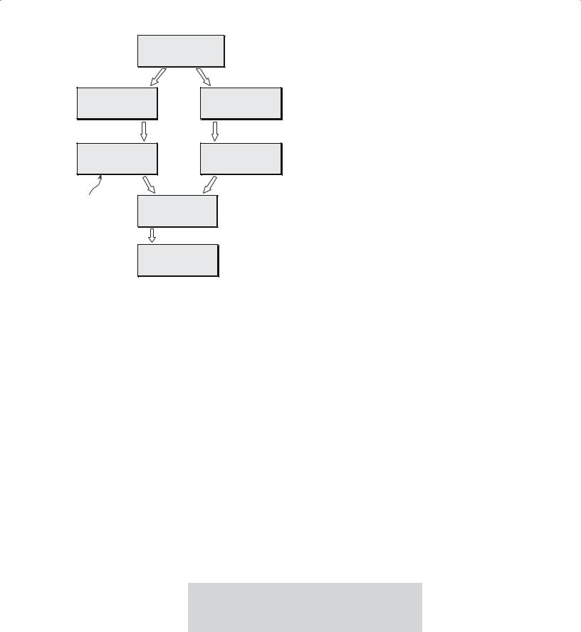
form this into a gel. In ceramic synthesis, two different |
the processes is shown in Figure 22.1. |
|
|
|
|
||||
sol-gel routes have been identified and depend on the gel |
In this chapter we are concerned only with the poly- |
||||||||
structure. |
|
|
meric gel route because this is the approach that is most |
||||||
|
|
|
|
useful to |
ceramists. This |
||||
Particulate |
gel—using |
|
|
method has been success- |
|||||
DEFINITION OF SOL AND GEL |
|||||||||
a network of colloidal |
ful in preparing a range of |
||||||||
Colloidal particles or molecules are suspended in a |
|||||||||
particles |
|
advanced |
ceramics such |
||||||
|
liquid or solution, a “sol.” The sol is mixed with another |
||||||||
Polymeric |
gel—using |
as lead |
zirconate |
titanate |
|||||
liquid, which causes formation of a continuous three- |
|||||||||
an array of polymeric |
(PZT) |
and |
the |
high-Tc |
|||||
dimensional network, a “gel.” |
|
||||||||
chains |
|
|
oxide superconductors. |
||||||
|
|
|
|||||||
400 ......................................................................................................................... |
S O L S , G E L S , A N D O R G A N I C C H E M I S T R Y |
|
Solution of |
|
|
Metal Alkoxides |
|
hydrolysis & |
hydrolysis |
|
condensation |
||
|
||
Sol |
Sol |
|
(solution) |
(suspension: particles) |
|
gelation |
gelation |
|
‘Polymeric’ |
‘Particulate’ |
|
Gel |
Gel |
|
drying |
drying |
|
Forming |
|
|
network |
Dried Gel |
|
|
firing
Dense Product
FIGURE 22.1 Flow chart comparing sol-gel processing using a solution and a suspension of fine particles.
TABLE 22.1 Examples of Metal Alkoxides |
|
|
Name |
Chemical formula |
Physical state |
|
|
|
Aluminum S-butoxide |
Al(Os C4H9)3 |
Colorless liquid, |
|
|
TB 203°C |
Aluminum ethoxide |
Al(OC2H5)3 |
White powder, |
|
|
TM 130°C |
Aluminum isopropoxide |
Al(Oi C3H7)3 |
White powder, |
|
|
TM 118.5°C |
Antimony ethoxide |
Sb(OC2H5)3 |
Colorless liquid, |
|
|
TB 95°C |
Barium isopropoxide |
Ba(Oi C3H7)2 |
Off-white powder |
Boron ethoxide |
B(OC2H5)3 |
Colorless liquid, |
|
|
TB 117.4°C |
Calcium methoxide |
Ca(OCH3)2 |
Off-white powder |
Iron ethoxide |
Fe(OC2H5)3 |
TM 120°C |
Iron isopropoxide |
Fe(Oi C3H7)3 |
Brown powder |
Silicon tetraethoxide |
Si(OC2H5)4 |
Colorless liquid, |
|
|
TB 165.8°C |
Silicon tetraheptoxide |
Si(OC7H15)4 |
Yellow liquid |
Silicon tetrahexoxide |
Si(OC6H13)4 |
Colorless liquid |
Silicon tetramethoxide |
Si(OCH3)4 |
Colorless liquid, |
|
|
TB 121–122°C |
Titanium ethoxide |
Ti(OC2H5)4 |
Colorless liquid, |
|
|
TB 122°C |
Titanium isopropoxide |
Ti(Oi C3H7)4 |
Colorless liquid, |
|
|
TB 58°C |
Yttrium isopropoxide |
Y(Oi C3H7)3 |
Yellowish-brown |
|
|
liquid |
|
|
|
The significant advantage of sol-gel processing of ceramic powders is that homogeneous compositions can be prepared at temperatures lower than required for conventional powder processes. Furthermore, the reactants used in sol-gel processing are available in very high purities, which allows the formation of high-purity powders of crystalline ceramics and glasses.
A commonly studied approach for synthesizing oxides has been to hydrolyze the appropriate metal alkoxides. There are several advantages to using metal alkoxides as precursors for ceramic powders. Most of the alkoxides of interest can be easily prepared or are commercially available and can be readily purified prior to use. Interaction of alkoxides with water yields precipitates of hydroxides, hydrates, and oxides. The precipitate particles usually range in size from 0.01 to 1 μm, depending on the hydrolysis conditions. So we can easily produce nanoparticles.
22.2 STRUCTURE AND SYNTHESIS OF ALKOXIDES
Alkoxides have the general formula M(OR)z where M is usually a metal, but can also be a nonmetal such as Si, and R is an alkyl chain. Table 22.1 lists some
common alkoxides used in the preparation of ceramics. The nomenclature adopted for the simple alkoxides
follows the basic rules of organic chemistry:
Methoxide |
R = CH3 |
Example is B(OCH3)3 |
Ethoxide |
R = C2H5 |
Example is Si(OC2H5)4 |
Propoxide |
R = C3H7 |
Example is Ti(OiC3H7)4 |
|
R = C4H9 |
(n- and iso-) |
Butoxide |
Example is Al(OsC4H9)3 |
|
|
|
(n-, iso-, sec-, and tert-) |
In these molecular formulas, the superscripts n, t, s, and i refer to normal, tertiary, and secondary or isoalkyl chains, each of which is illustrated for the butoxide group in Figure 22.2. These are common names and do not follow the Commission on the Nomenclature of Organic Chemistry of the International Union of Pure and Applied Chemistry (IUPAC). In the case of higher alkoxides, i.e., those with five or more C atoms, the nomenclature is derived strictly from IUPAC conventions. For example, the alkoxide group (CH3)3CCH2CH2O– would be referred to as 2,2-dimethylbutoxide. The old name is neohexoxide.
Most metal alkoxides contain lower aliphatic alkyl groups and are coordinated complexes and not single molecules. Figure 22.3 shows an example of a coordination complex of aluminum isopropoxide consisting of three molecules.
Even when using the IUPAC convention there is still the distinct possibility of encountering confusion when reading the literature. For example, silicon tetraethoxide
2 2 . 2 S T R U C T U R E A N D S Y N T H E S I S O F A L K O X I D E S ....................................................................................................... |
401 |
n-butoxide |
|
C H 3 C H 2 C H 2 C H 2 O |
|
|
|
|
|||||||||||||||
|
|
H |
|
|
H |
|
|
H |
|
H |
|
|
|
|
|||||||
H |
|
|
|
|
|
|
|
|
|
|
|
|
|
|
|
|
|
|
|
|
|
|
C |
|
|
C |
|
|
C |
|
C |
|
|
|
O |
|
|
||||||
|
|
|
|
|
|
|
|||||||||||||||
|
|
|
|
|
|
|
|
|
|
|
|
|
|
|
|
|
|
|
|
|
|
|
|
H |
|
|
H |
|
|
H |
|
H |
|
|
|
|
|||||||
|
|
|
|
|
|
||||||||||||||||
s-butoxide |
C H 3 C H 2 C H O C H 3 |
|
|
|
|
||||||||||||||||
|
|
H |
|
|
H |
|
|
H |
|
H |
|
|
|
|
|||||||
H |
|
|
|
|
|
|
|
|
|
|
|
|
|
|
|
|
|||||
|
C |
|
|
C |
|
|
C |
|
C |
|
|
H |
|||||||||
|
|
|
|
|
|
|
|
||||||||||||||
|
|
|
|
|
|
|
|
|
|
|
|
|
|
|
|
|
|
|
|||
|
|
H |
|
|
H |
|
|
O |
|
H |
|
|
|
|
|||||||
|
|
|
|
|
|
|
|
|
|
|
|
|
|
|
|
|
|
|
|
|
|
|
|
|
|
|
|
|
|
|
|
|
|
|
|
|
|
|
|
|
|
|
|
isobutoxide |
|
|
( C H 3 ) 2 C H C H 2 O |
|
|
|
|
||||||||||||||
|
|
|
|
H 3 C |
|
|
H |
|
|
|
|
|
|
|
|
|
|||||
|
|
H |
|
|
|
|
|
|
|
|
|
O |
|
|
|
|
|
||||
|
|
|
|
C |
|
|
C |
|
|
|
|
|
|
||||||||
|
|
|
|
|
|
|
|
|
|
|
|
|
|||||||||
|
|
|
|
|
|
|
|
|
|
|
|
|
|
|
|
|
|
|
|
|
|
|
|
|
|
H 3 C |
|
|
H |
|
|
|
|
|
|
|
|
|
|||||
|
|
|
|
|
|
|
|
|
|
|
|
||||||||||
t-butoxide |
|
( C H 3 ) 3 C O |
|
|
|
|
|
|
|
|
|
||||||||||
|
|
|
|
H 3 C |
|
|
|
|
|
|
|
|
|
|
|
|
|
|
|||
|
H 3 C |
|
|
C |
|
|
O |
|
|
|
|
|
|
|
|
|
|
||||
|
|
|
|
|
|
|
|
|
|
|
|
|
|
|
|||||||
|
|
|
|
|
|
|
|
|
|
|
|
|
|
|
|
|
|
|
|
||
|
|
|
|
H 3 C |
|
|
|
|
|
|
|
|
|
|
|
|
|
|
|||
FIGURE 22.2 Illustration of nomenclature for metal alkoxides.
TABLE 22.2 Alkoxides of Metals with Different
Electronegativities
|
Electronegativity |
|
Alkoxide |
of metal |
State |
|
|
|
Na(OC2H5) |
0.9 |
Solid (decomposes above |
|
|
530 K) |
Ba(Oi C3H7)2 |
0.9 |
Solid (decomposes above |
|
|
400 K) |
Y(Oi C3H7)3 |
1.2 |
Solid (sublimes at 475 K) |
Zr(Oi C3H7)4 |
1.4 |
Liquid (boiling point 476 K |
|
|
at 0.65 kPa) |
Al(Oi C3H7)3 |
1.5 |
Liquid (boiling point 408 K |
|
|
at 1.3 kPa) |
Ti(Oi C3H7)4 |
1.5 |
Liquid (boiling point 364.3 K |
|
|
at 0.65 kPa) |
Si(OC2H5)4 |
1.8 |
Liquid (boiling point 442 K |
|
|
at atmospheric pressure) |
Fe(OC2H5)3 |
1.8 |
Liquid (boiling point 428 K |
|
|
at 13 Pa) |
Sb(OC2H5)3 |
1.9 |
Liquid (boiling point 367 K |
|
|
at 1.3 kPa) |
B(On C4H9)3 |
2.0 |
Liquid (boiling point 401 K |
|
|
at atmospheric pressure) |
Te(OC2H5)4 |
2.1 |
Liquid (boiling point 363 K |
|
|
at 0.26 kPa) |
|
|
|
may be referred to as tetraethylsilicate, tetraethylorthosilicate (TEOS), and tetraethoxysilane!
The first alkoxide to be synthesized was silicon tetraisopentoxide (formerly called silicon tetraisoamyloxide), made by a reaction between silicon tetrachloride and isopentanol (formerly isoamyl alcohol):
SiCl4 + 4(CH3)2CHCH2CH2OH → Si(O(CH3)2CHCH2CH2)4 + 4HCl (22.1)
Many alkoxides are available commercially, particularly those of Si, Al, Ti, B, and Zr. These are not generally
PriO |
|
OPri |
Pri |
Al |
Pri |
O |
|
O |
expensive materials, for example, TEOS, a colorless liquid, costs about $40/kg. However, nonstandard alkoxides, for example, Ba(OC2H5)2, are more expensive. Barium isopropoxide is an off-white powder and costs about 250 times as much as TEOS ($10/g). A 10% w/v solution of Ba(OC2H5)2 in ethanol will cost about $2/ml.
22.3 PROPERTIES OF ALKOXIDES
The properties of metal alkoxides depend on the electronegativity of the metal. Pauling’s electronegativity scale was given in Chapter 3.
Alkoxides of alkali metals, e.g., sodium alkoxides, and alkaline earth metals are ionic solids. Alkoxides of Ge, Al, Si, Ti, and Zr are often covalent liquids. Since most alkoxides are either liquids or volatile solids (examples are given in Table 22.2), they can be purified by distillation to form exceptionally pure oxide sources as shown in Table 22.3.
PriO |
Al |
Al |
OPri |
TABLE 22.3 Effect of Distillation on the Purity of Silicon |
||||||
|
|
|
|
Tetraethoxide |
|
|
|
|
|
|
|
O |
|
|
Form/impurity |
Mn |
Cr |
Fe |
Co |
Ni |
Cu |
|
PriO |
|
OPri |
|
|
|
|
|
|
|
|
|
As supplied |
10 |
15 |
86 |
0.7 |
<200 |
<200 |
||
|
|
|
|
|||||||
|
Pri |
|
|
(ppb) |
0.8 |
2 |
31 |
0.3 |
11 |
<20 |
|
|
|
|
Once distilled |
||||||
FIGURE 22.3 Three-molecule coordination complex of aluminum |
(ppb) |
|
isopropoxide. |
||
|
||
|
402 ......................................................................................................................... |
S O L S , G E L S , A N D O R G A N I C C H E M I S T R Y |

|
|
Hydrolysis |
|
|
Drying |
|
|||||
|
& |
|
|
|
& |
|
|
|
|||
|
Condensation |
|
|
Firing |
|
||||||
|
Sol |
|
|
|
|
Gel |
|
|
|
Oxide |
|
|
|
|
|
|
|
|
|
product |
|
||
|
|
|
|
|
|
|
|
|
|
|
|
|
|
|
|
|
|
|
|
|
|
|
|
|
|
|
|
|
|
|
|
|
|
|
|
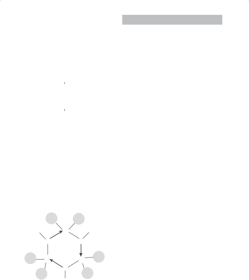
FIGURE 22.4 The basic steps in the sol-gel process using metal alkoxides.
22.4 THE SOL-GEL PROCESS USING METAL ALKOXIDES
The three basic steps in the sol-gel process are summarized in Figure 22.4. The conversion of the sol to a gel occurs by hydrolysis
and condensation reactions. The gel is converted into the oxide by drying and firing. We will now look at each of these steps in a little more detail.
Preparing the Sol
The sol-gel process can be used to make single or multicomponent oxides. First we will consider the case of a one-component system—silica. Of the many available silicon alkoxides, TEOS is commonly used. It is insoluble in water, but water is necessary for the hydrolysis reaction; hence we need to select a solvent for both the alkoxide and water. Ethanol is a suitable solvent, and a typical formulation contains three main components: 43 vol% Si(OC2H5)4, 43 vol% C2H5OH, and 14 vol% H2O.
For small-scale sol-gel processing in the laboratory the equipment is relatively simple and inexpensive:
Three-necked flask (contains the mixed solutions)
Mechanical stirrer (the mixture is stirred constantly)
Reflux condenser (needed to prevent the solution from evaporating)
Constant temperature bath (the rate of hydrolysis depends on temperature)
Multicomponent sols can be prepared by mixing different precursors, which are selected to give eventually an oxide of the desired composition. Table 22.4 gives examples of typical formulations for both single-component and multicomponent alkoxide solutions. There may be problems if the hydrolysis rates of the precursors are different, and this can create inhomogeneities in the subsequent gel. We can allow for this possibility by partially hydrolyzing the less reactive component [e.g., Si(OC2H5)4] before adding the more reactive one [e.g., Ti(OiC3H7)4].
For some metals, such as the alkali metals and alkaline earth metals, it is not possible or it is inconvenient to use alkoxides because they are either unavailable or difficult to prepare. You can see from Table 22.2 that alkoxides of these metals are solids
with low volatility. In many cases they also have low solubility. In these situations alternative reactants must be found. Metal salts such as acetates and citrates, which are soluble in organic solvents, are a viable alternative. Many of these can be obtained in a high-purity analytical grade. In cases in which we use both alkoxides and metal salts it is usual to first form a solution of all the components that are to be added as alkoxides. Then add the salts as solutions in alcohol or, if this is not possible, in the water that is to be used for the hydrolysis reaction. The final solution is homogenized by stirring.
TABLE 22.4 Formulations for Single-Component and Multicomponent Alkoxide Solutions |
|
|
|
|
|
|||||||||
|
|
|
|
|
|
|
|
|
|
|
Three components: |
|
||
|
One component: |
|
|
Two components: |
|
|
15 mol% Li2O + 3 mol% |
|
||||||
|
100 mol% SiO2 |
|
|
94 mol% SiO2 + 6 mol% TiO2 |
|
Al2O3 + 82 mol% SiO2 |
|
|||||||
|
|
|
|
|
||||||||||
|
|
|
|
|
||||||||||
|
|
|
|
|
|
|
|
|
|
|
|
|
|
|
|
|
Oxide |
|
|
|
|
Oxide |
|
|
|
|
Oxide |
|
|
|
|
|
|
|
|
|
|
|
|
|
|
|||
|
|
|
|
|
|
|
|
|
|
|
|
|||
|
Solution |
content |
|
|
|
Solution |
content |
|
|
|
Solution |
content |
|
|
|
concentration |
(vol%/ |
|
|
concentration |
(vol%/ |
|
|
|
concentration |
(vol%/ |
|
|
|
Precursor |
(wt%/100 g) |
100 ml) |
mol |
g/mol |
|
(wt%/100 g) |
100 ml) |
mol |
g/mol |
|
(wt%/100 g) |
100 ml) |
mol |
g/mol |
|
|
|
|
|
|
|
|
|
|
|
|
|
||
Si(OC2H5)4 |
45 |
43 |
|
|
11 |
11 |
|
|
35 |
34 |
|
|
||
Ti(OC3H7)4 |
|
|
|
|
1 |
1 |
|
|
|
|
|
|
|
|
Al(OC4H9)3 |
|
|
|
|
|
|
|
|
|
1 |
1 |
|
|
|
LiNO3 |
|
|
|
|
|
|
|
|
|
3 |
1 |
|
|
|
C2H5OH |
40 |
43 |
4 |
|
36 |
41 |
14 |
|
29 |
34 |
4 |
|
||
H2O |
16 |
14 |
4 |
|
52 |
47 |
50 |
|
33 |
30 |
8 |
|
||
Oxide (Si + Ti + |
|
|
1 |
11.3 |
|
|
|
1 |
3.15 |
|
|
|
1 |
10.6 |
Al + Li)
2 2 . 4 TH E S O L - G E L P R O C E S S U S I N G M E T A L A L K O X I D E S ............................................................................................. |
403 |
|
RO |
|
Silicon |
|
RO |
H |
H+ |
RO |
OR |
H+ |
|
|
|
|
tetraethoxide |
|
|
|
|
H |
|
||||
|
|
|
|
|
|
|
|
|
||||
|
|
|
|
|
|
|
O |
+ |
|
OR |
OR |
|
HO- |
+ |
Si |
OR |
OH |
Si |
OR |
Si |
O |
||||
|
||||||||||||
|
RO |
|
|
|
|
|
|
RO |
|
|
Si |
|
|
|
OR |
|
RO |
OR |
H |
OR |
H |
|
|||
|
|
|
|
|
|
|
|
|||||
|
|
|
|
|
|
|
|
RO |
|
|||
Base |
|
|
|
|
|
|
|
|
|
OR |
||
|
|
|
|
|
|
Acid |
|
|
|
|||
|
|
|
|
|
|
|
|
|
|
|
||
|
|
|
|
|
|
|
|
Acid-catalyzed |
|
|
||
Insoluble |
|
RO |
|
Condensation |
Same as |
hydrolysis |
|
|
|
|||
in water |
|
|
|
|
(eliminate HOR) |
before |
|
|
|
|
|
|
|
|
|
|
|
|
R |
|
|
|
|||
so dissolve |
|
|
|
|
|
|
|
|
|
|
|
|
|
|
|
|
|
|
|
|
|
|
|
||
in EtOH |
|
Si |
+ -OR |
|
|
|
|
|
|
|
||
|
OH |
|
|
|
|
O |
H |
+ |
OR |
|||
|
|
|
|
|||||||||
|
|
|
|
|
|
|
|
H |
+ |
|
||
|
|
|
|
|
|
|
|
|
|
|
||
|
|
RO |
|
|
OR |
|
|
|
O |
|
Si |
|
|
|
|
|
|
|
|
|
|
|
|
|
|
(A) |
|
|
|
|
|
|
H |
|
|
|
||
|
|
|
|
|
|
|
|
|
RO |
|
|
OR |
|
|
|
|
|
|
|
|
|
|
|
|
|
|
|
|
|
|
|
|
|
|
|
|
|
|
(B)
FIGURE 22.5 Schematic showing reaction mechanisms for (a) acidand (b) base-catalyzed hydrolysis of silicon alkoxides.
Hydrolysis and
Condensation
Metal alkoxides undergo hydrolysis very easily (meaning they react with water). In many cases they are so sensitive to moisture
that special precautions must be taken in handling and storage (e.g., the use of an N2 glove box and dehydrated solvents). The product vendor will provide information on the sensitivity of the compound.
During the initial stage of hydrolysis an alcohol molecule, ROH, is expelled.
M(OR)z + H2O → M(OH)(OR)z−1 + ROH (22.2)
This is an example of a condensation reaction involving the elimination of an alcohol (e.g., ethanol).
The hydroxy metal alkoxide product can react by a further condensation reaction to form polymerizable species.
M(OH)(OR)z−1 + M(OR)z → |
|
(RO)z−1MOM(OR)z−1 + ROH |
(22.3) |
2M(OH)(OR)z−1 → (RO)z−1MOM(OR)z−1 + H2O |
(22.4) |
Hydrolysis can be carried out either under basic or acidic conditions as shown in Figures 22.5 for TEOS. In the context of sol-gel processing, acid-catalyzed conditions are defined as pH <2.5; base-catalyzed conditions are defined as pH >2.5. Of course, this is not our usual definition of acid and base, where a neutral pH is 7, but corresponds to the point of zero charge (PZC) at which the surface is electrically neutral.
Hydrolysis may go to completion leading to the formation of the silicic acid monomer. But this generally does not occur except at low pH and high water concentrations.
The silicic acid monomer is not stable and condensation of silanol groups (Si–OH) leads to polymer formation before silanol groups substitute for all the alkoxy groups. This
process is illustrated for a general case in Figure 22.6a.
Self-condensation
|
|
RO |
|
|
|
|
|
|
|
|
|
|
|
RO |
|
|
|
|
|
|
|
|
|
|
|
|||||
|
|
|
|
|
|
|
|
|
|
|
|
|
|
|
|
|
|
|
|
|
|
|
|
|
|
|
|
|
|
|
RO |
|
|
M |
|
OR + H2O |
|
|
|
|
|
ROH + RO |
|
M |
|
|
OH |
|
|
|
|
|
|
||||||||
|
|
|
|
|
|
|
|
|
|
|
|
|
|
|
|
|||||||||||||||
|
|
|
|
|
|
|
|
|
|
|
|
|
|
|
|
|
|
|
|
|
|
|
|
|
|
|
|
|||
|
|
|
|
|
|
|
|
|
|
|
|
|
|
|
|
|
|
|
|
|
|
|
|
|
|
|
|
|
|
|
|
|
RO |
|
|
|
|
|
|
|
|
|
|
|
RO |
|
|
|
|
|
|
|
|
|
|
|
|||||
|
|
RO |
|
|
|
RO |
|
|
|
|
|
|
|
|
RO |
|
RO |
|
||||||||||||
|
|
|
|
|
|
|
|
|
|
|
|
|
|
|
|
|
|
|
|
|
|
|
|
|
|
|||||
RO |
|
|
M |
|
OH + RO |
|
|
M |
|
|
OR |
|
ROH + RO |
|
|
M |
|
O |
|
M |
|
OR |
||||||||
|
|
|
|
|
|
|
|
|
|
|
|
|
||||||||||||||||||
|
|
|
|
|
|
|
|
|
|
|
|
|
|
|
|
|
|
|
|
|
|
|
|
|
|
|
|
|
||
|
|
RO |
|
|
|
RO |
|
|
|
|
|
|
|
|
RO |
|
RO |
|
||||||||||||
(A) |
|
|
|
|
|
|
|
|
|
|
|
|
|
|
|
|
|
|
|
|
|
|
|
|
|
|
|
|
|
|
|
|
|
|
|
|
|
|
|
|
|
|
|
|
|
|
|
|
|
|
|
|
|
|
|
|
|
|
|
||
|
|
|
|
|
|
|
|
|
|
|
|
|
|
|
|
|
|
Polymerization |
|
|||||||||||
|
|
|
|
|
|
|
|
|
|
|
|
|
|
|
|
|
|
|
|
|
||||||||||
|
|
|
|
|
|
|
|
|
|
|
|
|
|
|
|
|
|
|
|
|||||||||||
Cross-condensation |
|
|
|
|
|
|
|
|
|
|
|
|
|
|
|
|
|
|
|
|||||||||||
|
|
RO |
|
|
|
|
|
|
|
|
|
|
|
RO |
|
|
|
|
|
|
|
|
|
|
|
|||||
|
|
|
|
|
|
|
|
|
|
|
|
|
|
|
|
|
|
|
|
|
|
|
||||||||
RO |
|
|
M |
|
OR + H2O |
|
|
|
|
|
ROH + RO |
|
M |
|
|
OH |
|
|
|
|
|
|
||||||||
|
|
|
|
|
|
|
|
|
|
|
|
|
|
|
|
|
||||||||||||||
|
|
|
|
|
|
|
|
|
|
|
|
|
|
|
|
|
|
|
|
|
|
|
|
|
|
|
|
|
||
|
|
|
|
|
|
|
|
|
|
|
|
|
|
|
|
|
|
|
|
|
|
|
|
|
|
|
|
|||
|
|
RO |
|
|
|
|
|
|
|
|
|
|
|
RO |
|
|
|
|
|
|
|
|
|
|
|
|||||
|
|
RO |
|
|
|
RO |
|
|
|
|
|
|
|
|
RO |
|
RO |
|
||||||||||||
|
|
|
|
|
|
|
|
|
|
|
|
|
|
|
|
|
|
|
|
|
|
|||||||||
RO |
|
|
M |
|
OH + RO |
|
|
M* |
|
OR |
|
ROH + RO |
|
|
M |
|
O |
|
M* |
OR |
||||||||||
|
|
|
|
|
|
|
|
|
|
|
||||||||||||||||||||
|
|
|
|
|
|
|
|
|
|
|
|
|
|
|
|
|
|
|
|
|
|
|
||||||||
|
|
RO |
|
|
|
RO |
|
|
|
|
|
|
|
|
RO |
|
RO |
|
||||||||||||
(B) |
|
|
|
|
|
|
|
|
|
|
|
|
|
|
|
|
|
|
|
|
|
|
|
|
|
|
|
|
|
|
|
|
|
|
|
|
|
|
|
|
|
|
|
|
|
|
|
|
Polymerization |
|
|||||||||||
|
|
|
|
|
|
|
|
|
|
|
|
|
|
|
|
|
|
|
|
|
||||||||||
|
|
|
|
|
|
|
|
|
|
|
|
|
|
|
|
|
|
|
|
|
|
|
|
|
|
|
|
|
|
|
FIGURE 22.6 Schematic showing condensation reactions in
(a) single metal alkoxide solutions and (b) mixed metal alkoxide solutions.
404 ......................................................................................................................... |
S O L S , G E L S , A N D O R G A N I C C H E M I S T R Y |
For different metal alkoxides the situation is shown in Figure 22.6b.
The experimental variables used in the first stage of the sol-gel process determine the kinetics of the hydrolysis of the sol to form a gel and have a major influence on gel structure. The relevant variables are
Alkoxide concentration
Reaction medium
Concentration of catalyst [The rates of hydrolysis and condensation can be affected by the addition of small
amounts of acid (e.g., HCl) or base (e.g., NH4OH), respectively.]
Temperature
The Sol-Gel
Transition
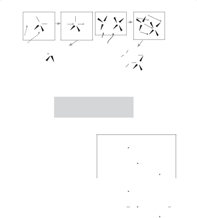
Viscosity is a key parameter that is used to determine when the sol-gel transition occurs. At the transition there is an abrupt increase in viscosity. The
structural changes that occur during gelation for acidcatalyzed and base-catalyzed reactions are illustrated in Figure 22.7.
Viscosity can be measured by two simple methods:
Capillary flow—most common
Rotation—using “Couette flow”
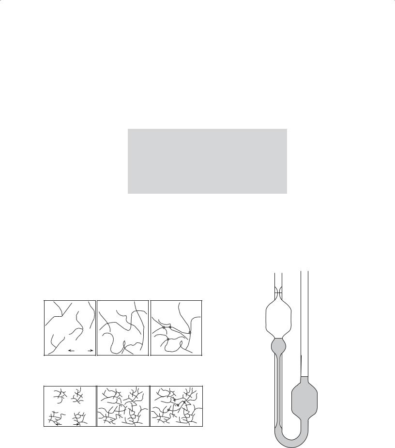
The Ostwald viscometer, illustrated in Figure 22.8, is an example of a capillary method used to study the sol-gel
10 nm |
Far From Gel Point
(A)
Near Gel Point Entangled primarily linear molecules
Gel Point
Additional crosslinks at junctions
transition. The solution is introduced into the viscometer such that it reaches levels B and C. Liquid is then drawn up into the left-hand limb until the liquid levels are above A and at the bottom of the right-hand bulb. When the liquid is released the time for the left-hand meniscus to pass between marks A and B is measured. Since the pressure at any instant driving the liquid through the capillary is proportional to its density we write
η = kρt |
(22.5) |
where k is a constant known as the viscometer coefficient, ρ is the density of the liquid, and t is the flow time. The capillary measurement is simple to operate and quite precise (0.01–0.1%).
Rotational methods are particularly suitable for studying the flow of nonNewtonian liquids. An
example is the concentric cylinder (or Couette) viscometer. The liquid is sheared between concentric cylinders, which are moving relative to one another. The outer cylinder can be rotated (or oscillated) at a constant rate and the shear measured in terms of the deflection of the inner cylinder, which is suspended by a torsion wire. Alterna-
A
B
C
10 nm |
|
|
Far From Gel Point |
Near Gel Point |
Gel Point |
Branched clusters |
Growth and |
Linked clusters |
|
additional branching |
|
(B) |
|
FIGURE 22.7 Illustration of (a) acidand (b) base-catalyzed |
FIGURE 22.8 An Ostwald viscometer. The liquid is initially at B |
polymerization and gelation. |
and C, then is drawn up to A. |
2 2 . 4 TH E S O L - G E L P R O C E S S U S I N G M E T A L A L K O X I D E S ............................................................................................. |
405 |

tively, the inner cylinder can be rotated with the outer cylinder stationary and the resistance offered by the motor measured. The coefficient of viscosity is given by
η = Kθ/ωh |
(22.6) |
where K is an instrument constant (usually obtained by calibration with a liquid of known η), ω is the angular velocity of the rotating cylinder, and h is the effective height of the liquid in contact with the cylinders. This method is essentially the same as the Mergules viscometer (Section 21.3) that is used to measure the viscosity of glass melts; the temperature is very different.
Drying and Firing
After gelation, the gel usually consists of a weak skeleton of amorphous material containing an interconnected network of small liquid-filled pores. The liquid is usually a mixture of alcohol and water, which must be removed. Shrinkage during this step is usually large.
There are several different methods used to dry gels. Each method produces a
dried gel with a specific microstructure. In most cases we obtain either an aerogel or a xerogel, but other microstructures are possible as shown in Table 22.5.
The drying process is complicated, particularly when we want to form monolithic ceramics. One problem is cracking, which is more likely with high drying rates and thick (>1 cm) gels. A number of procedures have been developed to increase drying rates while avoiding cracking:
Increase the pore size of the gel.
Decrease the liquid/vapor interfacial energy; e.g., use a solvent with a low γlv.
Strengthen the gel.
Use supercritical (hypercritical) drying: the liquid is
removed above its critical temperature, Tc, and critical pressure, pc. The values of Tc and pc for the commonly
TABLE 22.5 The Various Types of Dried Gels
used sol-gel liquids are water: 647 K and 22 MPa, and ethanol: 516 K and 6.4 MPa.
During firing, further changes occur as the gel densifies. The driving forces for these changes are as follows:
The large surface area of the dried gel. A xerogel has a solid/vapor interfacial area of 100–1000 m2/g. Reduction of the surface area provides a driving force for densification.
The low cross-linked density of the dried gel. The
free energy, Gf (298 K), of the polymerization −14.9 kJ/mol, and this acts asreaction (Eq. 22.7) is
a driving force for increasing the amount of cross-linking.
Si–OH + HO–Si → Si–O–Si +H2O (22.7)
Structural relaxation of the solid skeletal phase of the gel as the structure approaches that of a supercooled liquid (if the gel forms a glass) or a crystal line solid
(if the gel forms a crystalline ceramic).
22.5 CHARACTERIZATION OF THE SOL-GEL PROCESS
Many techniques, in addition to measuring viscosity changes, have been used to follow the transitions that occur during sol-gel processing. There are the two parts of the process in which we are interested:
1.The transition from sol to gel
2.The transition from gel to oxide
Examples of techniques used to characterize sol-gel processes and the type of information they can provide are listed in Table 22.6. We described most of these techniques in Chapter 10.
Type |
Drying conditions |
Microstructure |
|
|
|
Aerogels |
In an autoclave, the fluid is removed by hypercritical evacuation |
A network consisting of 95% porosity |
Xerogels |
Natural evaporation |
Dried gel has about 40–60% of the fired density and |
|
|
contains small pores (as small as 2 nm) |
Sonogels |
Gel exposed to ultrasound in the 20-kHz range prior to |
Assists in the formation of multicomponent gels |
|
autoclave treatment |
|
Cryogels |
Freeze dried |
Finely divided powder, not suitable for producing |
|
|
monolithic ceramics |
Vapogels |
A fluid stream of SiCl4 is injected into acidified water; this |
Allows incorporation of additives into the gel, |
|
allows rapid gel formation; the gel is then dried to a xerogel |
e.g., GeO2 if the fluid stream also contains GeCl4 |
|
|
|
406 ......................................................................................................................... |
S O L S , G E L S , A N D O R G A N I C C H E M I S T R Y |

TABLE 22.6 Methods Used to Characterize Sol-Gel Processes
Technique |
What is measured |
How it is used |
|
|
|
Ellipsometry |
Thickness, optical constants of films |
Fourier transform IR spectroscopy |
Vibrational frequencies of chemical bonds, |
|
qualitative and quantitative identification |
|
of functional groups |
Raman spectroscopy |
Vibrational frequencies of chemical bonds, |
|
compound identification, structural order |
|
and phase transitions |
Solid-state nuclear magnetic resonance |
Interaction between nuclear magnetic |
(NMR) spectroscopy |
moments in atoms in the sample with rf |
|
electromagnetic waves, sensitive indicator |
|
of structural and chemical bonding |
|
properties; phase identification and |
|
characterization of local bonding |
|
environment |
Transmission electron microscopy |
Crystallinity and phase identification by |
|
diffraction, microstructure at high spatial |
|
resolution |
X-ray diffraction |
Crystallinity and phase identification, |
|
averaged microstructural information |
To measure film thickness changes, for example, during drying
Chemical changes during gelation, drying, and firing
Chemical and structural changes during gelation, drying, and firing
Polymerization kinetics, time evolution of condensed species
The chemical shifts in 29Si NMR are functions of the state of silicon polymerization
Transformation from amorphous to crystalline during firing; experiments can be performed in situ
Transformation from amorphous to crystalline during firing; experiments can be performed in situ
22.6 POWDERS, COATINGS, FIBERS, CRYSTALLINE, OR GLASS?
Sol-gel processing is versatile because it can be used to produce ceramics in a number of different forms:
Powders—because we can make very small particles and control the composition
Example application: bioactive glass powders, with a composition of SiO2–CaO–P2O5
Coatings—because the sol is a viscous liquid and can be applied to a substrate by spinning
Example application: TiO2-based antiglare coatings on glass
Example application: coat steel with alumina to improve wear resistance
Fibers—because we can pull a thread out that is liquid and dry it, coat it, etc.
Example application: SiO2 fibers used for space shuttle tiles
Crystalline or Glass? We have the choice.
Example application: high-purity porous silica glass for filtration
Powders
Powders can be obtained via a sol-gel process using metal alkoxides or a combination of metal alkoxides and metal salts. Because the mixing of the constituents is achieved at a molecular level, the powders are chemically homogeneous. Powders produced by the sol-gel method are usually amorphous. This characteristic, together with their high surface area, allows them to be sintered to nearly full
density at temperatures lower than are normally required when the particles have been made by other techniques. For example, gel-derived mullite powders can be sintered to full density at <1300°C, whereas the sintering temperature is 1600°C for crystalline mullite powders. However, the cost of the raw materials limits the use of the sol-gel method in producing many ceramic powders except for those used for specialty applications.
Coatings and Films
Ceramic coatings can be prepared using a sol-gel process involving metal alkoxides. The coatings may be formed by
Dipping
Spinning
Spraying
Lowering (similar to dipping except the substrate remains stationary and the liquid is lowered)
Spinning is widely used for applying sol-gel coatings, and one particular application is to produce thin coatings of PZT for microelectromechanical systems (MEMS). Alkoxide-derived coatings are used for both antireflective layers on glass substrates and solar reflecting coatings on flat glass. Table 22.7 lists a number of applications for sol-gel films and coatings.
The advantages of forming coatings via sol-gel reactions are
Large areas
Uniform composition
2 2 . 6 P O W D E R S , C O A T I N G S , F I B E R S , C R Y S T A L L I N E , O R G L A S S ? ................................................................................. |
407 |
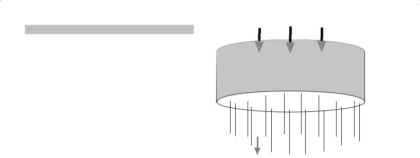
TABLE 22.7 Applications of Sol-Gel Films and Coatings
Field |
Property |
Examples |
|
|
|
Electronic |
Ferroelectric |
BaTiO3, PZT |
|
Piezoelectric |
PZT |
|
High-Tc superconductor |
YBa2Cu3O7 |
|
Ferrimagnetic |
Doped Fe2O3 |
|
Transparent conductors |
Indium tin oxide |
Optical |
Antireflective |
TiO2/SiO2 |
|
Solar reflecting |
TiO2/Pd |
|
Electrooptic |
PLZT |
Protective |
Corrosion resistant |
SiO2 |
|
Abrasion resistant |
Organic modified |
|
|
silicates |
|
Barrier films |
YSZ |
Biomaterials |
Bone cell regeneration |
Calcium apatites |
|
|
|
Conformal coating of irregularly shaped substrates, e.g., fibers
High purity
Microstructural control, i.e., pore volume (0–65%), pore size (<0.4 nm to >5.0 nm), and surface area (<1–250 m2/g)
Less expensive than vapor-phase processes such as chemical vapor deposition (CVD) and sputtering
Fibers
In Chapter 20 we described various methods of making ceramic fibers including the sol-gel process. Fibers can be drawn directly from viscous sols, which are usually made by acid-catalyzed hydrolysis using low H2O : M ratios. At viscosities greater than about 1 Pa·s (glycerine has a viscosity of 1 Pa·s at room temperature) the sol is sticky and we can produce fibers by forcing the sol through a spinnerette, illustrated in Figure 22.9. The spinnerette can be rotated to produce a yarn. This process is used commercially to produce polymer fibers.
Applications for sol-gel-derived fibers include
Reinforcement in composites
Refractory textiles
High-temperature superconductors
Examples of fibers produced by sol-gel are
Pressure
Spinnerette
Fibers extrude
FIGURE 22.9 Illustration of a spinnerette used to produce fibers and yarn.
SiO2
SiO2–TiO2 (10–50 mol% TiO2)
SiO2–Al2O3 (10–30 mol% Al2O3)
SiO2–ZrO2 (10–33 mol% ZrO2)
SiO2–Na2O–ZrO2 (25 mol% ZrO2)
The properties of some commercial sol-gel fibers are given in Table 22.8.
Glasses
Glasses can be synthesized using the sol-gel process. This process makes it possible to form a disordered glass network, not directly at high temperatures from the melt, but at low temperatures by chemical polymerization in a liquid.
The Owens-Illinois Company started an investigation of bulk glass systems formed by the sol-gel process in 1967. The dried gels were melted and fabricated by conventional techniques. They found the following advantages:
Lower melting temperatures could be used (the gel is already amorphous).
TABLE 22.8 Properties of Commercial Gel-Derived Ceramic Fibers |
|
|
|||
|
|
|
Tensile |
Tensile |
|
|
|
|
strength |
modulus |
Density |
Producer |
Name |
Composition |
(MPa) |
(GPa) |
(g/cm3) |
|
|
|
|
|
|
3M |
Nextel 312 |
Al2O3, SiO2, B2O3 |
1750 |
154 |
2.70 |
3M |
Nextel 440 |
Al2O3, SiO2, B2O3 |
2100 |
189 |
3.05 |
3M |
Nextel 480 |
Al2O3, SiO2, B2O3 |
2275 |
224 |
3.05 |
Du Pont |
PRD-166 |
Al2O3, ZrO2 |
2100 |
385 |
4.20 |
Du Pont |
FP |
α-Al2O3 |
1400 |
3853 |
3.90 |
Sumitomo |
|
Al2O3, SiO2 |
Average 2200 |
Average 230 |
3.20 |
|
|
|
|
|
|
408 ......................................................................................................................... |
S O L S , G E L S , A N D O R G A N I C C H E M I S T R Y |
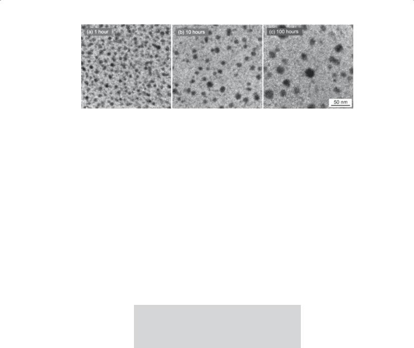
FIGURE 22.10 Use of sol-gel processing to produce Si nanoparticles in a glass matrix. (a–c) The time indicates the length of the heat treatment.
It was not necessary to stir the melt (the gel is homogeneous).
It was also found that glasses fabricated from gels and those of the same composition made from oxide powders had essentially the same physical properties. But the work was discontinued because of the high cost of the gels compared to the cost of the traditional powders. And, in terms of processing considerations, the gel must be heated very slowly to the melting temperature to ensure that any residual organics and water are removed, otherwise a very seedy and foamy melt can be obtained.
Sol-gel processing can really be justified only for glasses of certain compositions such as those with high melting temperatures and high viscosity glasses that are difficult to melt conventionally. But glass coatings made by the sol-gel process are still important commercially.
Monolithic Ceramics
There are basically two routes that can be used to produce monolithic ceramics via a sol-gel process:
Firing: use xerogels or aerogels
Compaction and firing: use gel-derived powders
Making monolithic ceramics directly by a sol-gel process is still a challenge. The main issue is how the gel can be dried without introducing cracks in the dried body. The advantages of using a sol-gel route compared
to conventional ceramic methods is that we are working in uncontaminated conditions and using lower temperatures.
The compaction-and-firing process is similar to traditional methods for producing ceramics from powders except that the powders are derived from the sol-gel process. The pros and cons are the same as those mentioned in forming powders using this method.
Particles in Sol-Gel Films
Since the sol-gel films are essentially amorphous in their as-prepared state, we can heat treat them to grow nanoparticles that are then embedded inside an amorphous matrix. The amorphous SiO(C) film in Figure 22.10 was produced by pyrolysis of a sol-gel precursor. The cohydrolysis of triethoxysilane and methyldiethoxysilane (in a molar ratio of 9 : 1) used addition of acidic water (pH 2.25)
to produce the xerogel. The xerogel was pyrolyzed at 1000°C for 1 hour to produce an Si-rich glass. The films were heated for a further 10 hours and then 100 hours to produce the images shown here.
The dark regions in the images are O depleted and Si rich. High-resolution transmission electron microscopy (HRTEM) showed that these were crystalline Si nanoparticles (which have potentially interesting luminescent properties). So not only does this type of study produce an interesting material, but it also sheds light on Ostwald ripening and devitrification of a glass.
CHAPTER SUMMARY
You should know that sols and gels are different concepts and that sol-gel uses both. You cannot avoid learning the basic organic chemistry: it is messy and has confusing terminology but is amazingly versatile and can produce nanomaterials routinely. Sol-gel processing is a method that can be used to form ceramic powders, thin films and coatings, fibers, and monolithic ceramics. The advantages of sol-gel processing are that we have excellent control of the
C H A P T E R S U M M A R Y .......................................................................................................................................................... |
409 |