

Ceramic materials Carter Horton / fulltext 23 Shaping and forming
.pdf23
Shaping and Forming
CHAPTER PREVIEW
This is the pottery chapter! Many of the techniques that are now being used to shape high-tech ceramics have been used by potters for millennia, but have been refined for today’s high-tech applications and for new ceramic materials. We will try to relate shaping to the potter’s craft throughout the chapter.
We can just process dry powder and sinter it, but it is much more common to add some amount of liquid, just as the potter adds water to clay; we then shape the object and fire it. Shaping transforms an unconsolidated powder mixture into a coherent, consolidated body having a chosen geometry. The selection of a shaping operation for a particular product is very dependent on the size and dimensional tolerances of the product, the requisite microstructural characteristics, the levels of reproducibility required, economic considerations, and of course the required shape. We cover shaping of glass in Chapters 21 and 26 so here we will consider the similarities in processing glass and crystalline ceramics. Similarly, we discuss thick films in Chapter 27; here we concentrate on three-dimensional (3D) objects varying from fish-hooks to turbine blades. However, we will cover slip casting, which we used only in a limited way for thin films.
23.1 THE WORDS
There is a special vocabulary for shaping ceramics because it is an ancient art. Once the constituent powders have been prepared in the desired purity and particle size most ceramic products must be fabricated into useful shapes. Many shaping methods are used for ceramic products and these can be grouped into three basic categories, which are not necessarily independent.
1.Powder compaction: dry pressing, hot pressing, cold isostatic pressing, etc.
2.Casting: using a mold with the ceramic as, or containing, a liquid or slurry
3.Plastic forming: extrusion, injection molding, etc.— using pressure to shape the green ceramic
Powder compaction is simply the pressing of a freeflowing powder. The powder may be dry pressed (i.e., without the addition of a binder) or pressed with the addition of a small amount of a suitable binder. The pressure is applied either uniaxially or isostatically. The choice of pressing method depends on the shape of the final product. We make simple shapes by applying the pressure uniaxially; more complex shapes require isostatic pressing.
Casting ceramics is carried out at room temperature and generally requires the ceramic powder particles to be suspended in a liquid to form a slurry; note this process
is quite unlike the casting of metals. The slurry is then poured into a porous mold that removes the liquid (it diffuses out through the mold) and leaves a particulate compact in the mold. This process is known as slip casting. The process has been used to form many traditional ceramic products (e.g., sanitary ware) and more recently has been used in forming advanced ceramic products (e.g., rotor blades for gas turbines). The other main casting process for ceramics is tape casting, which, as you would guess, is used to make thick films or sheets and is described in Chapter 27.
Plastic forming consists of mixing the ceramic powder with a large volume fraction of a liquid to produce a mass that is deformable (plastic) under pressure. Such processes were developed and used originally for clay and have since been adapted to polymeric materials. For traditional claybased ceramics the liquid is mainly water. For ceramic systems that are not based on clay, an organic may be used in place of, or in addition to, water. The binders are often complex and contain multiple components to achieve the required viscosity and burn-out characteristics.
Table 23.1 lists the major methods that are included in each of the above categories and the types of shape that can be produced. First some of the words:
Binder is a component that is added to hold the powder together while we shape the body.
Slurry is a suspension of ceramic particles in a liquid.
412 .................................................................................................................................................... |
S H A P I N G A N D F O R M I N G |

TABLE 23.1 Various Shaping Methods for Ceramic Components |
|
|
Shaping method |
Type of feed material |
Type of shape |
|
|
|
Dry pressing |
Free-flowing granules |
Small and simple |
Isostatic pressing |
Fragile granules |
Larger and more intricate |
Extrusion |
Plastic mass using a viscous polymer solution |
Elongated with constant cross section |
Injection molding |
Organic binder giving fluidity when hot |
Complex |
Slip casting |
Free-flowing cream |
Mainly hollow |
|
|
|
Plasticizer is the component of a binder that keeps it soft or pliable; it improves the rheological properties.
Green is a ceramic before it is fired. Brown, white, or gray potter’s clays are well known green ceramics.
Slip is the liquid-like coating used to form the glaze when fired.
Some of the shaping methods we will describe in this chapter produce a ceramic compact that is strong enough to be handled and machined; however, it is not fully dense and the bonds between the grains are not strong. This is called the “green” state and represents a transition state between the loose powder and the high-density sintered product. Other shaping methods, those that involve the use of high temperatures and pressures, can directly produce a very dense sintered product. Much of what we talk about here has a parallel in the field of powder metallurgy; the theme is often processing powders, which are not necessarily ceramic powders (e.g., they could be pharmaceuticals).
23.2 BINDERS AND PLASTICIZERS
It is often necessary to add a binder to the ceramic powder. The binder has two functions. In some shaping methods, such as extrusion, the binder provides the plasticity necessary for forming. The binder also provides the dry (green) shape with strength sufficient to survive the handling process between shaping and sintering. One of the most important requirements for the binder is that we must be able to eliminate it from the compact during the firing process without any disruptive effect: polymers are thus often ideal binders.
In pottery, the binder is often water that is present in sufficient quantity to make the clay easily shaped with the shape being retained during firing. The idea is that we then add a plasticizer to opti-
mize the rheology of the material. Note that these processes are not exclusive to ceramics but are general to powder processing. The distinction between binder and plasticizer is sometimes not too clear.
Binders can also be used when metal powders are processed; PMC is precious-metal clay.
23.3 SLIP AND SLURRY
The word slip appears to come (according to Webster’s) from the Old English words meaning cream: the suspension of curds in the liquid when making cheese; the cheese was actually sieved through a “slippe clothe.”
In general, slip consists of fine (<10 μm) ceramicpowder particles that are suspended in a fluid. In the pottery industry, the liquid is usually water. The suspension can have a solid content up to 60 vol%. Deflocculents are added to the slip to modify the electrical environment of each particle so that the particles repel each other.
Deflocculants: Since deflocculation is defined as the process by which floccules present in a liquid break up into fine particles producing a dispersion, a deflocculant is an additive that causes this process. In other words, deflocculation is the opposite of coagulation. (A floccule is a small piece of matter or a flock.)
Colloids: Colloids are defined very generally as any substance that consists of particles substantially larger than ordinary molecules but much too small
to be visible without optical magnification |
( 1 nm |
to 10 μm). They can be linked or bonded |
together |
in various ways. Colloidal systems can take several |
|
forms; the one relevant to us is the dispersion of one |
|
substance in another. Brownian motion has interested |
|
scientists for generations. Slip is a colloid. We can |
|
change the properties of the slip by adding flocculants or deflocculants.
Slurry: Clay particles are suspended in a liquid (water in the case of pottery). As the amount of water is decreased it becomes more solid. Glazes used in pottery have the same base as the clay but with more water content. Potter’s clay is made by first producing a slip from naturally occur-
2 3 . 3 S L I P A N D S L U R R Y ................................................................................................................................................... |
413 |
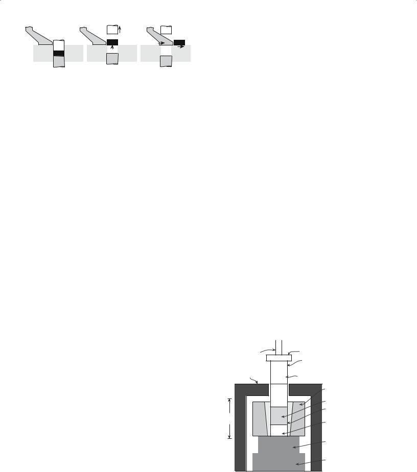
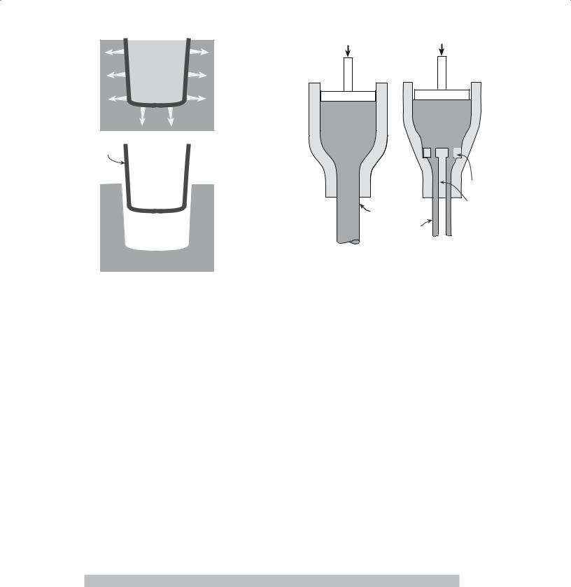
FIGURE 23.1 The stages in dry pressing.
ring clays. The slip is repeatedly filtered to produce a consistency that is constant over long periods of manufacture. Slabs of clay are then formed from this colloid by allowing most of the water to evaporate. The final product may be shaped by extrusion and packaged to prevent further loss of water.
23.4 DRY PRESSING
Dry pressing is ideally suited to the formation of simple solid shapes and consists of three basic steps: filling the die, compacting the contents, and ejecting the pressed solid.
Figure 23.1 shows a schematic diagram of the doubleaction dry-pressing process. In a double-action press both the top and bottom punches are movable. When the bottom punch is in the low position a cavity is formed in the die and this cavity is filled with free flowing powder. In dry pressing the powder mixture will contain between 0 and 5 wt% of a binder. (So, dry does not imply that there is no binder.) Once the cavity has been filled, the powder is struck off level with the top of the die. The top punch descends and compresses the powder either to a predetermined volume or to a set pressure. During pressing the powder particles must flow between the closing punches so that the space between them is uniformly filled. A particle size distribution of between 20 and 200 μm is often preferred for dry pressing: a high volume fraction of small particles causes problems with particle flow and also results in sticking of the punches. The pressures used in dry pressing may be as high as 300 MPa, depending upon material and press type, to maximize the density of the compact. After pressing, both punches move upward until the bottom punch is level with the top of the die and the top punch is clear of the powder-feeding mechanism. The compact is then ejected, the bottom punch is lowered, and the cycle is repeated.
Because the dry-pressing process is so simple and involves low capital equipment costs it is the most widely used high-volume forming process for ceramics. Production rates depend on the size and shape of the part and on the type of press used. For large components such as refractories or complex parts such as grinding wheels the production rates are 1–15 parts per minute. During a tour of the Wedgwood factory, you will see dinner plates being dry pressed in a continuous process. Simpler or smaller
shapes such as seal rings and nozzles can be produced at rates up to several hundred per minute. Small flat parts such as insulators, chip carriers, or cutting tools can be produced at rates up to several thousand per minute.
23.5 HOT PRESSING
Pressing can also be performed at high temperatures; this process is known as hot pressing. The die assembly used for hot pressing is very similar to that described in Section 23.4 for dry pressing. The main difference is that in hot pressing the die assembly is contained within a hightemperature furnace as shown in Figure 23.2. During hot pressing the ceramic powders may sinter together to form a high-density component.
We can summarize the advantages of this process.
The powder does not have to be of the highest quality.
Large pores that are caused by nonuniform mixing are easily removed.
We can densify at temperatures lower (typically half the melting temperature of the material) than those needed for conventional pressureless sintering.
Extensive grain growth or secondary recrystallization does not occur when we keep the temperature low during densification.
We can densify covalently bonded materials such as B4C, SiC, and Si3N4 without additives.
The principal disadvantage is also important.
Dies for use at high temperatures are expensive and do not generally last long.
Hydraulic |
Cooled platen |
press |
High-strength |
|
|
Furnace insulative |
refractory block |
|
|
refractory lining |
Refractory punch |
|
|
|
Mold |
|
Powder |
|
Replaceable |
Hot |
mold liner |
zone |
Plug |
|
Mold |
|
support |
|
block |
|
Refractory |
|
block |
FIGURE 23.2 Schematic showing the essential elements of a hot |
|
press. |
|
414 .................................................................................................................................................... |
S H A P I N G A N D F O R M I N G |
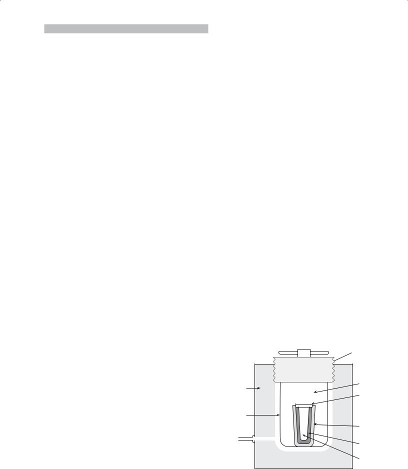
TABLE 23.2 Hot Pressed Products
Product |
Types of material |
|
|
Optical windows |
IR: MgF2, ZnS, ZnSe; visible: Y2O3, |
|
MgAl2O4 |
Ceramic armor |
B4C, TiB2, SiC, Al2O3 |
Cutting tools |
Al2O3 particle-reinforced TiC, Si3N4, |
|
Si3N4–AlN–Al2O3 |
Tooling (molds and dies) |
Al2O3–SiCw composites, SiC, Al2O3 |
Sputtering targets |
Cr–SiO, TiN, Si3N4, B4C, Al2O3 |
Heat engine components |
Si3N4, SiC |
Ceramic bearings |
Si3N4 |
Microwave absorbers |
MgO–SiC particulate composites, |
|
BeO–SiC, Al2O3–SiC |
Varistors |
ZnO |
Electrooptic materials |
PLZT |
Titanates |
BaTiO3, CaTiO3 |
Microelectronic packages |
Cofired W-metallized AlN |
Resistors |
Si3N4 matrix with particulates of TiB2, |
|
TiC, TiN, or SiC as the dispersed |
|
conducting phase |
|
|
Most metals are of little use as die materials above 1000°C because they become ductile, and the die bulges. Special alloys, mostly based on Mo, can be used up to 1000°C at pressures of about 80 MPa. Ceramics such as Al2O3, SiC, and Si3N4 can be used up to about 1400°C at similar pressures. Graphite is the most widely used die material and can be used at temperatures up to 2200°C and pressures between 10 and 30 MPa. The difficulty is that a graphite die will tend to produce a very reducing environment. (You can make an Al2O3 sample vanish using a graphite die!)
However, graphite does have many properties that make it suitable for a die.
small grain size, a high density (low porosity), or low impurity levels. Examples of such products are given in Table 23.2.
Isostatic pressing involves the application of hydrostatic pressure to a powder in a flexible container. The advantage of applying pressure in all directions is that there is more uniform compaction of the powder and more complex shapes can be produced than with uniaxial pressing. Isostatic pressing can be performed either with or without applied heat.
23.6 COLD ISOSTATIC PRESSING
There are many variations on using the cold isostatic press (CIP); here we just emphasize some basic themes. Figure 23.3 illustrates the so-called wet-bag CIP process. Powder is weighed into a rubber bag and a metal mandrel is inserted that makes a seal with the mouth of the rubber bag. The sealed bag is placed inside a high-pressure chamber that is filled with a fluid (normally a soluble oil/ water mixture) and is hydrostatically pressed. The pressures used can vary from about 20 MPa up to 1 GPa depending upon the press and the application. For production units the pressure is usually ≤400 MPa. Once pressing is complete, the pressure is released slowly, the mold is removed from the pressure chamber, and the pressed component is removed from the mold.
The advantages of the wet-bag process are
Wide range of shapes and sizes can be produced
Uniform density of the pressed product
Low tooling costs The disadvantages are
It is easy to machine (but the dust is toxic if inhaled— |
|
|
|
like coal dust). |
Poor shape and dimensional control (particularly for |
||
It is inexpensive. |
complex shapes) |
|
|
Its strength increases with increasing temperature. |
|
|
|
It has good creep resistance. |
|
|
|
It has excellent thermal conductivity. |
|
Breach-lock or |
|
It has a relatively low coefficient of thermal |
|
||
|
pressure cover |
||
expansion. |
|
|
|
Hot pressing, like dry pressing, is limited to simple |
Pressure |
Fluid |
|
solid shapes, such as flat plates, blocks, and cylinders. |
|
||
|
|
||
More complex or large shapes are difficult and often |
vessel |
Mold |
|
|
|
||
impossible to produce by hot pressing. Hot pressing is |
|
seal |
|
widely used in the research laboratory for processing very |
Wire |
plate |
|
|
|
||
dense, high-purity ceramic components. Although it is |
mesh |
|
|
basket |
Rubber |
||
extensively used in university and government laborato- |
|
||
|
mold |
|
|
ries, the technique is limited as a production tool because |
|
|
|
of its high cost and low productivity. For any mass- |
Pressurization |
Powder |
|
produced ceramic product there would be considerable |
source |
Metal |
|
commercial pressure for a company to find a less expen- |
|
|
|
|
mandrel |
||
sive alternative. However, some commercial hot-pressed |
|
|
|
ceramic products are available. These products require a |
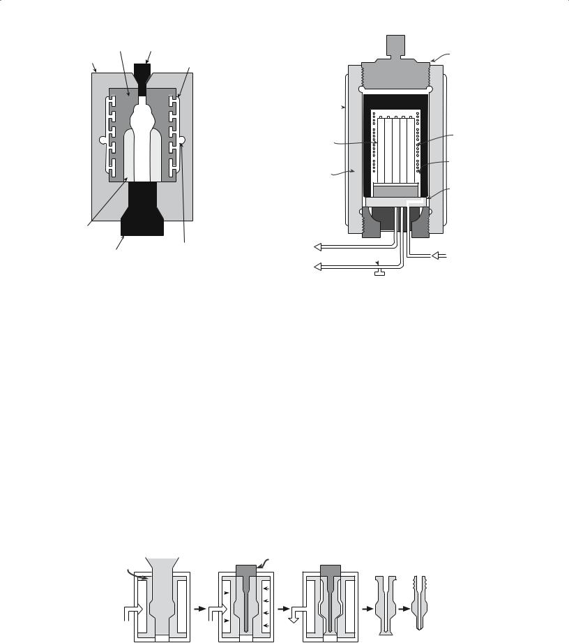
FIGURE 23.3 Schematic of a wet-bag isostatic pressing system. |
||
2 3 . 6 C O L D I S O S T A T I C P R E S S I N G ..................................................................................................................................... |
415 |
||
First
elastomer Cap
Rigid die case |
|
Channel to |
|
distribute liquid |
|
|
|
|
|
|
|
|
|
|
Second elastomer
Spindle |
Entry port for |
pressurized liquid |
FIGURE 23.4 Schematic of a die for dry-bag isostatic pressing of a spark plug insulator.
Upper cover
Cooling jacket
Components |
Heater |
|
ThermoPressure couple vessel
Power connection
To pump
Over-pressure release
Gas in
FIGURE 23.6 Schematic of a hot isostatic pressing apparatus.
Products often require green machining (described in Section 23.14) after pressing
Long cycle times (typically between 5 and 60 minutes) give low production rates
A small wet-bag isostatic press, used to produce laboratory samples and low-volume production parts, might have an internal diameter of 150 mm and a depth of 460 mm. Large wet-bag presses may have cavity diameters >1.8 m and lengths up to 3.7 m. The wet-bag CIP process can be automated.
A schematic diagram of a mold for the dry-bag CIP is shown in Figure 23.4. The main distinction of the dry-bag process is that the rubber mold is now an integral part of the press. The high-pressure fluid is applied through channels in the mold. After pressing, the pressed part is removed without disturbing the mold. Hence, the dry-bag press can be readily automated. Fully automated units are widely available and have been operating in the highvolume production of ceramic parts for over 20 years.
Production rates of up to 1 part per second are being achieved industrially.
The dry-bag CIP has been used for many years to press spark plug insulators. The steps in this process are shown in Figure 23.5. Notice the insertion of the inner pin in the mold. The world’s largest producers of spark plugs produced by this method are Champion and AC Spark Plug.
23.7 HOT ISOSTATIC PRESSING
The hot isostatic press (HIP) uses the simultaneous application of heat and pressure. We refer to this process as HIPing and the product as being HIPed (but you will see variations on these abbreviations). A furnace is constructed within a high-pressure vessel and the objects to be pressed are placed inside. Figure 23.6 shows a typical HIP arrangement. Temperatures can be up to 2000°C and pressures are typically in the range of 30–100 MPa. A gas
Rubber |
Powder |
Inner |
|
pin |
|||
container |
|||
|
|
At air |
Oil in |
Oil out |
FIGURE 23.5 Making spark plugs. Hydrostatic pressure is applied by pumping oil around the rubber container, which is part of the press and thus easily removed.
416 .................................................................................................................................................... |
S H A P I N G A N D F O R M I N G |
is used as the pressure medium, unlike the CIP in which a liquid is often used. Argon is the most common gas that is used for HIPing, but oxidizing and reactive gases can also be used. Note that the high-pressure vessel is not inside the furnace.
There are two variants of HIPing:
Encapsulated: using a deformable container
Not encapsulated: it is shaped and sintered first, then HIPed
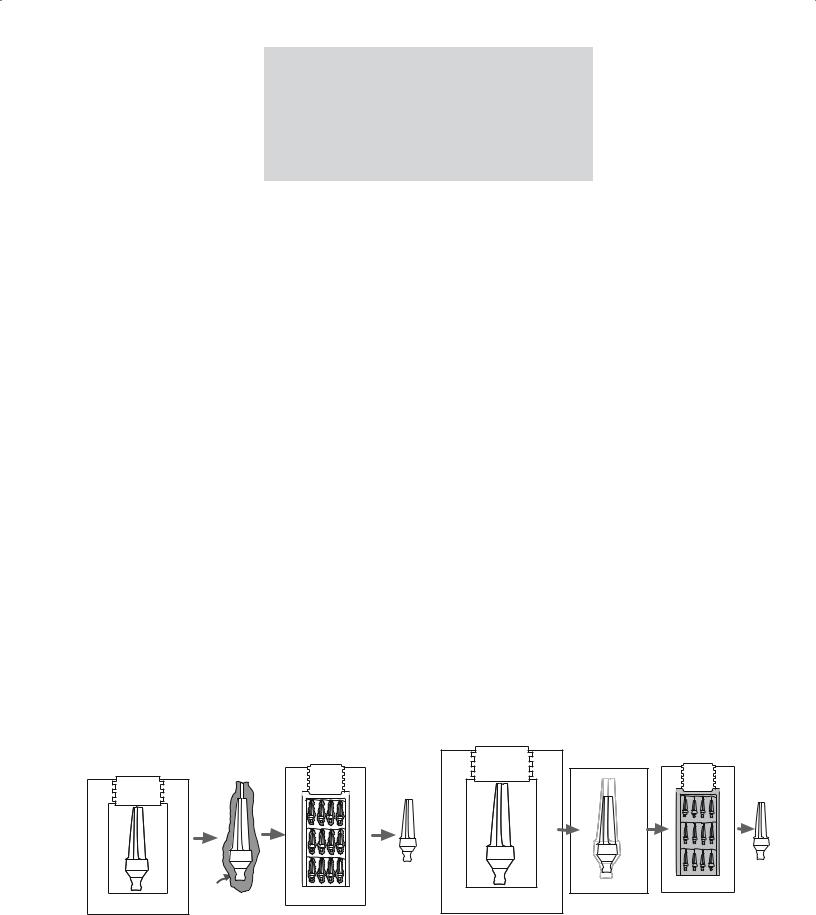
In the original HIPing method the ceramic powder was filled into a deformable metal can and then subjected to heat and pressure. This method was subsequently modified for small particle sized powders. The powder compact was preformed to the desired shape by a process such as dry pressing or injection molding. The green compact was then encapsulated in a glass envelope that could be removed from the product after HIPing as shown in Figure 23.7.
The second variant does not involve encapsulation. The ceramic powder is first compacted using another shaping method such as dry pressing or injection molding. It is then sintered at relatively high temperatures in a furnace to close all the surface pores, which prevents the entry of the gas during subsequent HIPing. The steps in this process, which is sometimes referred to as sinter-plus- HIP, are shown in Figure 23.8.
Now HIPing is used for a wide variety of ceramic (and metallic) components, such as alumina-based tool bits and the silicon nitride nozzles used in flue-gas desulfurization plants by the utility industry. The advantages of the HIPing process are becoming more important as interest in structural ceramics such as Si3N4 grows.
Nonoxide ceramics can be HIPed to full density while keeping the grain size small and not using additives. Very high densities combined with small grain sizes (because of the relatively low temperatures) lead to products with
special mechanical properties. HIPing has also been applied to the formation of piezoelectric ceramics such as BaTiO3, SrTiO3, and lead zirconate titanate (PZT) for use in acoustic wave filters and oscillators.
Uses: produces dense materials without growing the grains
Disadvantage: cost
23.8 SLIP CASTING
The slip is poured into a mold (usually plaster of Paris: 2CaSO4·H2O) that has been made by casting round a model of the required shape, which was itself suitably enlarged to allow for the shrinkage of the cast ceramic on drying and sintering. The fineness of the powder (in the slip) and the consequent high surface area ensure that electrostatic forces dominate gravity so that settling does not occur. The electrochemistry of the slip is quite complex: Na silicate (or soda ash) is added to the slip to deflocculate the particles. The water passes, via capillary action, into the porous plaster leaving a layer of the solid on the wall of the mold. (We consider this model in Section 25.7.) Once a sufficient thickness has been cast, the surplus slip is poured out and the mold and cast are allowed to dry. These steps are shown in Figure 23.9. This variant of slip casting, which is the most widely used, is also called drain casting. A very effective technique used by some potters is to produce a multilayer slip, parts of which are removed before firing.
Slip casting is a low cost way to produce complex shapes and in the traditional pottery industry it is the accepted method for the production of teapots, jugs, and figurines, although handmade items will likely be handthrown. Large articles, such as wash-hand basins and other whitewares, are also mass produced by slip casting. (Whitewares are not necessarily white.) One of the telltale
|
Strip |
|
|
can |
|
Glass |
|
|
envelope |
|
|
Canning |
HIP |
|
Preform |
||
|
||
FIGURE 23.7 Individual steps of cold preforming, canning, HIPing, |
||
and stripping in the standard HIPing process.
|
Sinter |
HIP |
Preform |
(shrinkage) |
|
|
|
FIGURE 23.8 Individual steps of cold forming, sintering, and HIPing in the sinter plus HIPing process.
2 3 . 8 S L I P C A S T I N G .......................................................................................................................................................... |
417 |
Force |
Force |
Slip |
|
(A) |
|
Green |
|
ceramic |
|
Spider
(B) Mold
FIGURE 23.9 Schematic illustrating the drain-casting process.
(a) Fill the mold with slip; the mold extracts liquid, forming a compact along the mold walls; (b) after excess slip is drained and after partially dryed, green ceramic is removed.
signs of a ceramic product made by slip casting is that it is hollow. Another variant of the slip casting process is solid casting. In solid casting, slip is continually added until a solid cast is made. These items will not be hollow— relatively, they will be heavier.
Slip casting is also used in the fabrication of some technical and structural ceramics. It is the standard method used to make alumina crucibles and has been successfully used to make complex structural ceramic components such as gas-turbine rotors. The technique of doctorblading, which we discuss in Chapter 27, is just another method of shaping the slip—ensuring that the slip is spread as a uniform layer.
23.9 EXTRUSION
Extrusion involves forcing a deformable mass through a die orifice (like toothpaste from a tube). The process is widely used to produce ceramic components having a
Needle
Extruded rod
Extruded tube
(A) |
(B) |
FIGURE 23.10 Extrusion of (a) a rod and (b) a tube.
uniform cross section and a large length-to-diameter ratio such as ceramic tubes and rods as illustrated in Figure 23.10. Clay with a suitable rheology for the extrusion process (essentially a paste) can be made by controlling the amount of water. Clay-free starting materials, such as Al2O3, are mixed with a viscous liquid such as polyvinyl alcohol or methylcellulose and water to produce a plastically deformable mass. Table 23.3 lists the compositions of some extrusion bodies. Extrusion of polymers has been used since the 1860s; it was originally used to process natural rubber. An extrusion press like those shown in Figure 23.11 is standard equipment in the potter’s barn.
Extrusion is also used to produce the alumina shells for sodium vapor lamps and the honeycomb-shaped catalyst supports for automotive emission-control devices (see Chapter 37). The catalyst supports are designed to give a high surface area and can consist of hundreds of open cells per square centimeter with wall thicknesses <100 μm. To produce these shapes, cordierite ceramic powder is mixed with a hydraulic-setting polyurethane resin. The mix is extruded into a water bath at a rate that matches the rate of cure of the polyurethane (about 2 mm/s). It is then fired to produce the final ceramic.
TABLE 23.3 Examples of Compositions of Extruded Bodies (Composition in vol%)
|
Refractory alumina |
|
High alumina |
|
Electrical porcelain |
|
|
|
|
|
|
|
|
|
|
|
Alumina (<20 μm) |
50 |
Alumina (<20 μm) |
46 |
Quartz (<44 μm) |
16 |
|
|
Hydroxyethyl cellulose |
6 |
Ball clay |
4 |
Feldspar (<44 μm) |
16 |
|
|
Water |
44 |
Methylcellulose |
2 |
Kaolin |
16 |
|
|
AlCl3 (pH > 8.5) |
<1 |
Water |
48 |
Ball clay |
16 |
|
|
|
|
MgCl2 |
<1 |
Water |
36 |
|
|
|
|
|
|
CaCl2 |
<1 |
|
418 |
|
|
|
|
|
|
|
|
|
|
|
S H A P I N G A N D F O R M I N G |
|||
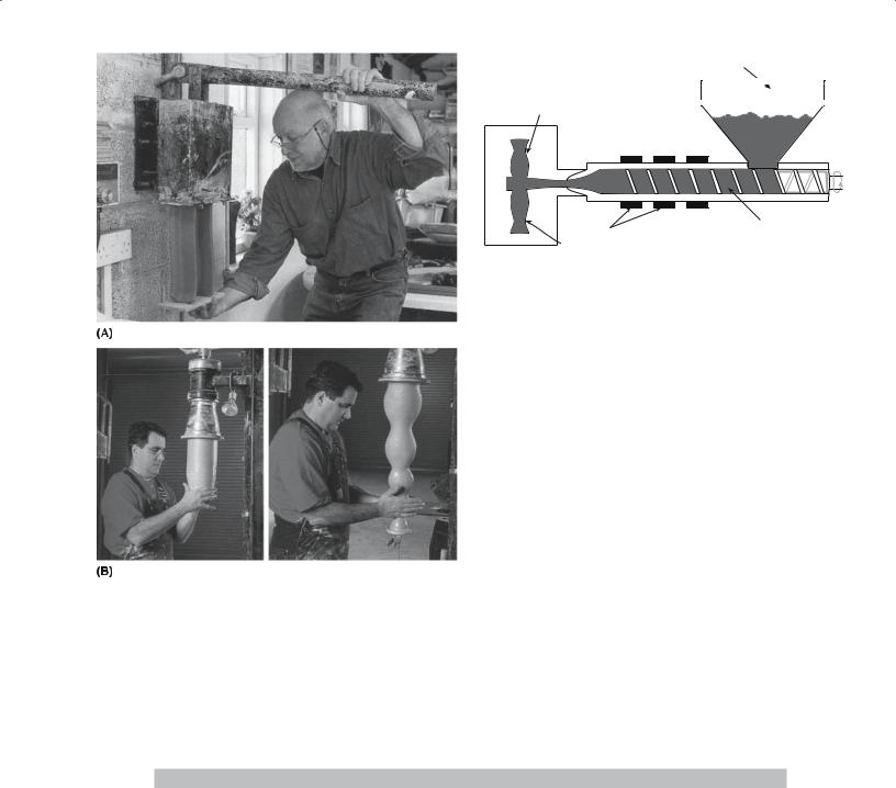
FIGURE 23.11 Extruding clay. Manual and electric extruders.
23.10 INJECTION MOLDING
Injection molding is another technique that is widely used in shaping thermoplastic polymers. A thermoplastic polymer is one that softens when heated and hardens when cooled. Such processes are totally reversible and may be
TABLE 23.4 Additives for Injection Molding of SiC
Hopper
Mold
Material 
Heaters |
Screw |
Green body |
|
FIGURE 23.12 Cross-sectional side view of a screw-type machine.
repeated. Injection molding can be applied to shaping and forming ceramic components if the ceramic powder is added to a thermoplastic polymer. When forming ceramics by injection molding, the polymer is usually referred to as the binder (but we could instead have called the material a ceramic-loaded polymer). The ceramic powder is added to the binder and is usually mixed with several other organic materials to provide a mass that has the desired rheological properties. Table 23.4 shows the additives that have been used to form SiC shapes by injection molding. The organic part of the mix accounts for about 40 vol%.
The plastic mass is first heated, at which point the thermoplastic polymer becomes soft and is then forced into a mold cavity as shown in Figure 23.12. The heated mixture is very fluid and is not self-supporting (this is different from the situation encountered in extrusion). The mixture is allowed to cool in the mold during which time the thermoplastic polymer hardens. Because of the large volume fraction of organic material used in the mixture, there is a high degree of shrinkage of injection-molded components during sintering. Shrinkage of 15–20% is typical, so precise control of component dimensions is difficult. However, complex shapes are retained with very little distortion during sintering since the densities, although low, are uniform.
Function |
Example |
Quantity (wt%) |
Volatilization temperature |
|
|
|
|
Thermoplastic resin |
Ethyl cellulose |
9–17 |
200–400°C |
|
Polyethylene |
|
|
|
Polyethylene glycol |
|
|
Wax or high-temperature volatilizing oil |
Paraffin |
2–3.5 |
150–190°C |
|
Mineral oils |
|
|
|
Vegetable oils |
|
|
Low-temperature volatilizing hydrocarbon or oil |
Animal oils |
4.5–8.5 |
50–150°C |
|
Vegetable oils |
|
|
|
Mineral oils |
|
|
Lubricant or mold release |
Fatty acids |
1–3 |
|
|
Fatty alcohols |
|
|
|
Fatty esters |
|
|
Thermosetting resin |
Epoxy |
|
Gives carbon |
|
Polyphenylene |
|
450–1000°C |
|
Phenol formaldehyde |
|
|
|
|
|
|
2 3 .10 I N J E C T I O N M O L D I N G ............................................................................................................................................. |
419 |
Injection molding is used to fabricate ceramic components with complex shapes; because cycle times can be rapid, injection molding can be a high-volume process. The major limitation is that the initial tooling costs of the mold can be quite high. The mold to fabricate an individual turbine blade can be >$10,000 and a mold for a turbine rotor may be >$100,000, but such molds are reusable since they are never subjected to high temperatures.
Heated |
Ceramic powder in |
|
extrusion |
||
thermoplastic |
||
nozzle |
||
polymer filament |
||
|
Green ceramic
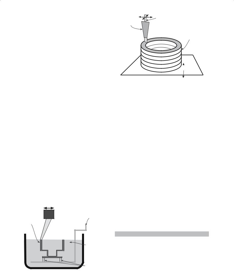
23.11 RAPID PROTOTYPING
Rapid prototyping (RP) or solid freeform fabrication (SFF) is a relatively recent approach to forming ceramic components. There are various forms of RP techniques, but they are based on a common principle: a computer directly controls the shaping process by accessing com- puter-aided design (CAD) files. We can thus use RP to form a 3D component without the use of a die or a mold. RP techniques are used commercially for fabrication of parts from polymers for design verification and form-and- fit applications; these techniques have more recently been applied to forming parts out of ceramics.
In this section we will look at just two of the several RP methods
Stereolithography (SLA)
Fused deposition modeling (FDM)
Both these methods have been successfully used to form ceramic components. The SLA process is illustrated in Figure 23.13. In SLA the component is formed from an epoxy resin. As the z-stage elevator is lowered, an ultraviolet (UV) laser beam whose position is controlled by a computer cures successive layers of the uncured resin. In this way a 3D component is made one layer at a time. It can take many hours to build a large complex object. But this is still rapid compared to the time taken to form a component by, e.g., injection molding, where fabrication of the tools can take a considerable amount of time. To form ceramic components by SLA the polymer must be
Scanner |
Movable |
System |
Table |
Green |
|
ceramic |
|
|
Ceramic |
|
powder |
|
in photo |
|
polymer |
|
Support |
|
structures |
FIGURE 23.13 Schematic representation of the SLA SFF process. |
|
 Platform
FIGURE 23.14 Schematic representation of the fused deposition (FD) SFF process.
loaded with ceramic powders. Si3N4, SiO2, and Al2O3 powders have all been used for SLA.
In FDM the source material is a thermoplastic polymer filament that is heated and extruded to form the product as shown in Figure 23.14. The product is formed in a layer- by-layer manner similar to building up layers of icing on a cake. The computer controls the x–y position of the filament and the deposition rate. The filament can be loaded with up to 60 vol% ceramic powders; once the part is completed the binder is removed and the part is sintered. Most of the work in the RP of ceramic parts by FDM has involved Si3N4. The feasibility of making components out of Al2O3, SiO2, and PZT has also been demonstrated. The abbreviation FDC (fused deposition of ceramics) is used to identify this special application of FDM.
23.12 GREEN MACHINING
To obtain the desired shape of a ceramic product it is often necessary to machine it. Machining can be performed either before or after the product has been sintered. If the machining is done before sintering, while the component is still in the green state, the process is called green machining. The advantages of green machining compared to machining the sintered product are that there is a considerable reduction (10×) in machining time and a 20× reduction in cost because of less tool wear and the possibility of using cheaper tools. Table 23.5 compares the use
TABLE 23.5 Comparison of Cutting Speed versus Tool Life
Tool |
Cutting speed |
Work-piece material |
Relative |
material |
(m/min) |
removed (cm3) |
cost factor |
|
|
|
|
Cubic BN |
30 |
8.2 |
× |
Ti-coated |
30 |
13.1 |
× |
carbide |
|
|
|
Co-coated |
30 |
19.7 |
× |
WC |
|
|
|
Diamond |
90 |
8500 |
10× |
|
|
|
|
420 .................................................................................................................................................... |
S H A P I N G A N D F O R M I N G |

of different tool materials in the green machining of an Si compact before nitriding it to form Si3N4.
In the processing of spark plug insulators the final processing step prior to firing involves green machining as shown earlier in Figure 23.5.
23.13 BINDER BURNOUT
In pottery, the binder burnout is the removal of water from the shaped clay. The rest of the firing process causes structure changes and transformations in the silicate itself. Forming methods for engineering ceramics, like injection molding, produce green bodies that can contain 30–50 vol% of organic binder. We generally want to remove this binder without cracking or distorting the ceramic compact. Binder burnout is one of the most likely stages to form defects in the processing of a ceramic: macroscopic defects, such as cracks and blisters, can be introduced at this stage, and these will affect the mechanical strength and other properties. An additional complication is that the binder system used in fabricating many commercial ceramic parts often consists of several components. These components have different boiling points and decomposition temperatures.
The components with low boiling points (e.g., waxes) may be removed by evaporation at fairly low temperatures.
Oxidation or decomposition at higher temperatures removes high-molecular-weight components.
For oxide ceramics, the binder can be oxidized to form H2O, CO, and CO2 when the green compact is heated in air. Binder burnout in air generally presents no problem. However, there are some situations in which binder burnout in air can be a problem. An example is the use of poly(vinyl butyral) with Al2O3 where carbon residues can be as high as thousands of parts per minute even after burnout in air at 700°C for 24 hours. Nonoxide ceramics generally cannot be heated in oxidizing environments and binder burnout in inert or reducing atmospheres is more difficult. Pyrolysis of many binders in these environments is not well understood and most binders leave some carbonaceous residue that could be detrimental to the subsequent sintering stage.
The process of binder removal is kept slow to reduce the possibility of macrodefects being produced. Figure 23.15 shows a plot of a binder removal cycle. In this plot a pressurized gas, called a sweep gas, has been passed over the part to help sweep away the vapor. The cycle time also depends on the size of the part. Thin sections take much shorter times than thick sections. The debinding time is proportional to the square of the section thickness of the compact—the familiar parabolic kinetics seen in our discussion of reactions in Chapter 25.
T °C |
|
|
|
|
|
1.33 x 10⁵ |
1200 |
|
|
|
|
|
1.33 x 10⁴ |
|
|
|
P |
|
T |
|
|
|
|
Sweep gas |
P (Pa) |
||
1000 |
|
|
|
|||
|
|
|
|
|
1.33 x 10³ |
|
|
|
|
|
|
Cool |
|
|
|
|
|
|
|
|
800 |
|
|
|
|
|
133 |
|
|
|
|
|
|
|
600 |
|
|
|
|
|
13.3 |
|
|
|
|
|
Sinter |
|
|
|
|
|
|
|
|
400 |
|
|
|
Polymer |
|
1.33 |
|
|
|
|
|
||
|
|
|
|
|
|
|
|
|
T |
|
removal |
|
|
200 |
Wax removal |
|
|
|
0.133 |
|
P |
|
|
|
|||
|
|
|
|
|
|
|
0 |
4 |
8 |
|
12 |
|
16 |
0 |
|
t (h) |
||||
|
|
|
|
|
|
FIGURE 23.15 Pressure-induced binder removal cycle.
Binder burnout continues to be an active area of ceramics research with one of the main thrusts being in developing models of binder decomposition and diffusion.
23.14 FINAL MACHINING
Ideally the shaping and forming processes that are employed would produce the ceramic component in the desired shape with the specified dimensional tolerances and with an acceptable surface finish. However, in many cases this is not the situation and some final machining (after firing/sintering) of the ceramic is necessary. Generally final machining is required to
Meet dimensional tolerances
Improve the surface finish
Remove surface flaws
Machining fired ceramics can be expensive and can represent a significant fraction of the total fabrication costs. Ceramic materials are difficult to machine because they are hard and brittle. The tooling costs are high because diamond tools are likely to be required or if conventional tools are used the tool life is very short. Also the time required to machine ceramics is long because if high tensile loads are applied to the ceramic part it might fracture.
Mechanical approaches to machining ceramics include the following:
Grinding uses tools in which abrasive particles are embedded in a softer matrix such as glass, rubber, or polymer resin, or even a metal (as for WC in Co).
Lapping uses loose abrasive particles placed on a soft cloth.
Sandblasting uses abrasive particles accelerated by compressed air and directed through a nozzle at high velocity.
2 3 .14 F I N A L M A C H I N I N G ................................................................................................................................................ |
421 |