Fig. 2. Dragline making first cut
Thus reverting to fig. 2, the excavation ABCD, approximately 100 feet by 30 feet, is dug by the machine while standing at points marked from 1 to 5. During this time, valueless overburden has been dumped on the unpayable ground at the side of the property where shown, at the same time the pay gravel has been dug and dumped into the washing plant according to the rate at which it has been uncovered. The hopper unit and launder stands with its centre line about 15 feet from the edge of the first cut and parallel to it. The tailings, as shown, are led over the small bund that has been built across the bottom of the property, the stones being rejected from the grizzly on to the pile shown near C. It must be remembered that the portion of the excavation оf the first cut near С will be the last to be dug by the dragline and will be firm ground on which to carry the stones until the cut is practically completed, when the stones pile is removed, together with the overburden to the dump, while the machine stands at about the figure 5 on the sketch.
As soon as the cut is opened out near A and B, a pump would be installed to keep the excavation dry and supply water for washing; this latter supply might require augmenting according to local conditions. If water is scare it may be necessary to have a settling pool for the tailings from which water can be regenerated.
Fig. 3 shows how the machine operates the second cut. The path of the machine is not on a true arc with respect to the washing plant, but the size of the hopper of the latter gives sufficient marge to permit the machine dumping into the hopper, when working from position 3 marked. The overburden and stones are dumped into the excavation made by the first cut. The washing plant stands in the same relative position to the second cut as it did to the first cut - that is to say, on a parallel line to its previous line and 30 feet, the width of each cut, from it.
The elevation shows the relative positions of machine, cuts one and two, and overburden spoils from these cuts; it will be seen that at С the toe of the overburden spoil of the second cut is apparently encroaching on the toe of this cut. It must be remembered that the machine would have actually cut out the section CDEF in advance of the spoil pile, so that, in practice, the bedrock could be cleaned up before the dumped material could encroach on the pay gravel.
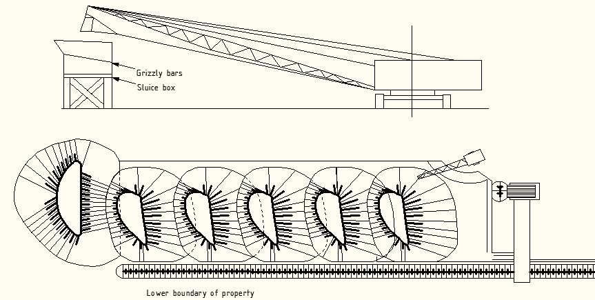
The third and subsequent cuts across the property until the opposite edge of payable ground is reached are practically similar to the second cut. Fig. 4 shows the machine finishing the sixth cut. The shape taken up by the overburden pile and other details are clearly shown; the whole rectangular piece ABHI has been worked. During this process it may have been necessary, according to the lie of the ground, to remove the pump from its first position suggested near D in fig. 2 to other positions in the excavation close to the line AI in fig. 4.
Fig. 5 shows the general arrangement of working the property with the boundaries and a number of cuts marked on it. In this sketch it will be noted that the machine has made one complete series of cuts across the width of the property, and is engaged on the second series of cuts. The machine has turned round, and the second series of cuts are being handled across from right to left instead of from left to right. This has several advantages as it will permit sufficient space on unpayable ground at the sides of the property to dispose of the overburden and stones from the first cut of each series of cuts.

Fig. 3. Dragline making second cut

Fig. 4. Dragline completine sixth cut
Fig. 5 shows the general arrangement of working the property with the boundaries and a number of cuts marked on it. In this sketch it will be noted that the machine has made one complete series of cuts across the width of the property, and is engaged on the second series of cuts. The machine has turned round, and the second series of cuts are being handled across from right to left instead of from left to right. This has several advantages, in that the move for the machine and washing plant at the end of the first series of cuts will only be a short one and that it will permit sufficient space on unpayable ground at the sides of the property to dispose of the overburden and stones from the first cut of each series of cuts.
The disposal of the overburden in the second series of cuts is the same as in the first series; the disposal of the tailings is effected by loading these in between the overburden dump piles in the old workings of the first series of cuts. This is done as shown in fig. 5: the machine, as it completes each cut not throwing up uniform piles of overburden as shown on the sketches, but filling up, with a small bund, the triangular sectional gaps between the overburden piles on the lines shown in fig. 5. The tailings from each of the cuts of the second series are led over this bund and dispersed in the area between spoil piles. By this means the toe of the second series of cuts is kept dry and clean working is ensured.