

Fig. 1.20. Edge dislocation in a crystal lattice

Fig. 1.21. Scheme of a screw dislocation
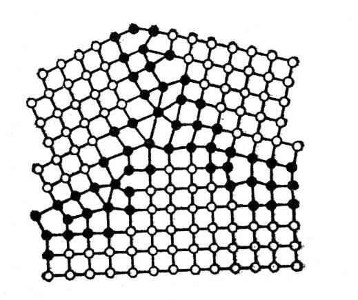
Fig. 1.22. Polycrystalline structure of metal
The grains of metal are usually oriented with respect to one another by angles ranging from several to dozens of degrees (high-angle boundaries). The atoms are arranged much less regularly at the grains boundary than within the volumes of the grains.
1.3.6. Theoretical and Engineering Strength of Metals
Based on the crystalline structure and interatomic forces we can theoretically estimate the force or the stress, required to cause slip or fracture in perfect crystal. To shear the crystal, two rows of atoms must be simultaneously displaced with respect to one another by shear stress (see Fig. 1.4.)
The theoretical shear stress is:
theor G/2,
where G is the shear modulus (analogous to tensile modulus E). But the theoretical strength, calculated by this formula, is from 100 to 1000 times as much as the real strength of engineering materials, or engineering strength.
There is no a mistake in theoretical calculations. The matter is that there is no simultaneous displacement of atoms in technical metals during their deformation and fracture. Dislocations are present in structure of real metals promoting the processes of slipping (sliding) and transference of atoms.
This way plastic deformation corresponds to the motion of large numbers of dislocations. An edge dislocation moves in response to a shear stress applied in a direction perpendicular to its line; the mechanics of dislocation motion is represented in Fig. 1.23.
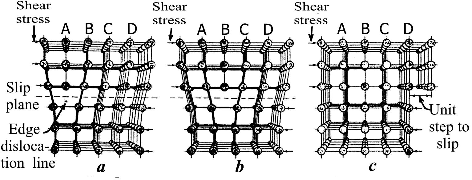
Fig. 1.23. Movement of an edge dislocation in shear
Let the initial extra half-plane of atoms be plane A. When the shear stress is applied as indicated (Fig. 1.23a), plane A is forced to the right; this in turn pushes the top halves of planes B, C, D, and so on, in the same direction. If the applied shear stress is of sufficient magnitude, the interatomic bonds of plane B are severed along the shear plane, and the upper half of plane B becomes the extra half-plane as plane A links up with the bottom half of plane B (Fig. 1.23b).
This process is subsequently repeated for the other planes, so that an extra half-plane moves from left to the right with discrete steps by successive and repeated breaking of bonds and shifting by interatomic distances of upper half-planes. Before and after the movement of a dislocation through some particular area of the crystal, the atomic arrangement is ordered and perfect; it is only during the passage of the extra half-plane that the lattice structure is disrupted. Ultimately this extra half-plane may emerge from the right surface of the crystal, forming an edge that is one atomic distance wide, which is shown in Figure 1.23c.
The process of plastic deformation by dislocation motion is called a slip. A plane along which the dislocation line traverses is termed a slip plane (Fig. 1.23c). Macroscopic plastic deformation simply corresponds to permanent deformation caused by the movement of dislocations, or slip in response to an applied shear stress.
The theoretical strength is strength of a perfect crystal (without dislocations). Due to this the theoretical strength is much higher than the engineering strength. The strength of metals is not a linear function of the dislocation density. As we can see at the diagram (Fig. 1.24), there are two main methods of increasing the strength:
- by producing metals and alloys of defectless structure;
- by increasing the density of defects, including dislocations, as well as structural barriers impeding the movement of dislocations.

Fig. 1.24 Dependence of the resistance to deformation on the number of defects (dislocation density) in metal: 1 - theoretical strength; 2 - strength of “whiskers”; 3 - pure unhardened metals;
4 - alloys strengthened by alloying, strain hardening, heat and thermomechanical treatment
The curve shows that the minimum strength corresponds to a certain critical dislocation density, equal approximately to 106… 108 cm-2. This value refers to annealed metals. As the number of defect reduces the resistance to deformation and the strength increase and rapidly approach the theoretical value. Crystals practically without dislocations may be produced. These filament-like crystals are small in size, from 2 to 10 mm long and 0.5 to 2 m (micrometers) thick, and are called “whiskers”. Their strength approaches the theoretical value. For example, the tensile strengths of such filament crystals of iron, copper and zinc are 13000; 3000 and 2250 MPa; their corresponding engineering strengths are 300; 260 and 180 MPa.
Any increase in size of the whiskers sharply reduces their strength. The whiskers are used for producing of fibrous (composite) materials. High strength and plasticity are obtained in this case by reinforcing a soft metallic matrix (copper, aluminum, silver, nichrome, etc.) or plastics (polymers) by defectless, filament-like crystal of metals or fibres of nonmetals ( -A12O3, carbon fibres, carbides B4C, SiC, etc.). The tensile strength of filament-like crystals amounts to 20000 MPa for A12O3, 7000 MPa for B4C 11000 MPa for SiC and 21000 MPa for carbon filaments.
If the number of defects (dislocations, point and surface defects, etc.) of the crystal structure exceeds 106...108 cm-2, its strength continues to raise. The relationship between the yield point y and the dislocation density p is:
![]() (1.17)
(1.17)
where 0 is shear stress before deformation (after annealing);
b is Burgers vector;
is strain hardening factor; depends upon the type of lattice and composition of the alloy.
This equation is the basis for all practical engineering methods of strengthening metals and alloys.
The dislocation density should not exceed 1012 or 1013 cm-2. At higher density the metal becomes brittle; and cracks are formed in it.
1.3.7. Diffusion
Many of the fundamental processes occurring in metals and alloys (crystallization, phase transformations, recrystallization, surface impregnation, etc.) are of diffusive nature. Diffusion refers to the displacement of atoms within a crystalline body over distances exceeding interatomic for the given substance.
In metals diffusion takes place predominantly by the substitutiuonal mechanism. Here, as it is shown at the Fig. 1.19 b, atom 1 has higher energy and can move into a vacancy. Thus, a new vacancy has been left at the previous location of this atom, which can be occupied by atom 2, etc.
Diffusion of the elements with a small atomic radius (C, N, H) in a metal takes place according to the interstitial mechanism.
The rate of diffusion is defined as the quantity of matter that diffuses through unit area of the interface in unit time. The higher concentration of diffusing element and temperature is, the higher the rate of diffusion.