

6.10. Gear - Cutting Methods
The two principal methods are employed in gears manufacturing: form cutting and generating. In form cutting process cutting tool with cutting edges formed to the shape of the tooth space to be cut is used. Gear-tooth milling cutters of the disk or end-mill type are examples of such tools (Fig. 6.20).
If a single tool is employed, the cutting alternates with indexing, i. e. turning the blank to the next tooth space or 1/z revolution, where z is the number of teeth of the gear. The production capacity of this method is low since each tooth space is machined separately, and time is lost in returning the tool to its initial position and indexing the gear blank.
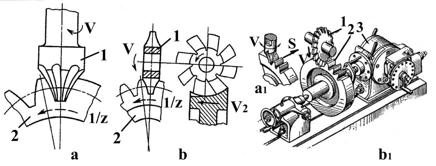
Fig. 6.20. Form gear-cutting: a, b – scheme; a1, b1 – drawing; 1 – cutting tool; 2 – billet;
3 – device for periodical turn of the billet on 1/z
In mass production the form cutting principle is applied in the multiple tool slotting cutter head used to cut all the tooth spaces of the gear at the same time (Fig. 6.21). This cutter head has as many radially arranged form tools as the number of teeth spaces (teeth ) in the gear to be cut. The profile of the tools is exactly of the same shape as the gear-tooth spaces. During each full stroke V (cutting and return ) of gear blank each tool is fed radially towards the blank Vr, by the amount equal to the infeed prior to each cutting stroke. All the tools by motion Vv of keeper 3 down are simultaneously retracted from the work in the return stroke to avoid rubbing of tool clearance surface against the machined surfaces. All the tooth spaces are cut simultaneously, and the gear is finished when the tools reach their full depth of cut.
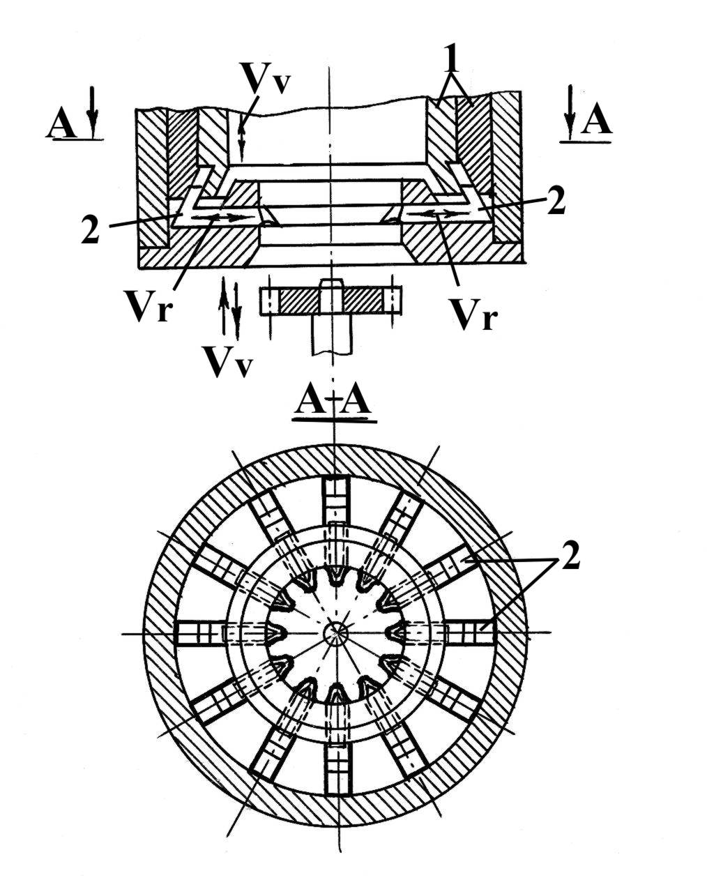
Fig. 6.21. Gear cutting by multiple tool slotting head: 1-gear; 2-radially arranged tools
The production capacity of this gear-cutting method is very high because accuracy of the cut gears depends only upon the accuracy of the cutter head, which may be sufficiently high.
Comparatively complex manufacture of the cutter heads and the necessity to have a separate head for each gear are among the drawbacks of this method.
The generating process is based upon the meshing of the cutter with gear being produced to develop the tooth by the relative rolling motion of the cutter and the work. For this purpose the cutter is shaped like a gear, gear rack or worm, i.e. a part which could mesh with the gear being cut; or the tool is made so that its cutting edges describe in space the surfaces of the tooth profiles of a certain imaginary gear or rack, known as the generating gear or rack.
In this general type of gear-cutting machines the cutting tool resembles either a gear and is called a rotary gear cutter (shaper), or a gear rack, in which case it is called a rack-type cutter.
A gear slotter (operating with the rotary type cutter 1) has the following principal motions (Fig. 6.22):
- straight line primary cutting motion V accomplished by travel of the cutter only in one direction (cutting stroke) and return of the cutter to the initial position (return stroke);
- continuous rotation of the cutter Vc and the gear blank Vb to obtain the circular feed (indexing motion);
- feeding motion (radial infeed) of the cutter Sc is obtained by travel of the cutter 1 axis in a direction towards the blank 2 axis with reciprocation of the blank Vb to avoid friction while return stroke.
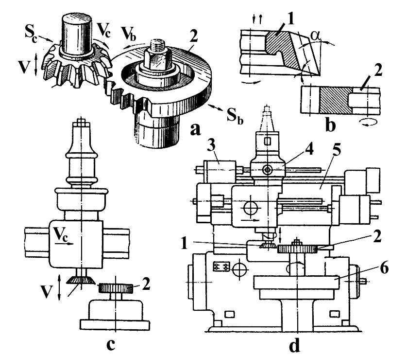
Fig. 6.22. Rotary type gear cutter: a – drawing; b – cutting angles of the cutter;
c – work part of gear-cutting machine; d – gear-cutting machine: 1 – cutter; 2 – blank;
3 – driving mechanism; 4 – cutting head; 5 – traverse; 6 – table