

6.8. Planing, Shaping and Slotting
Planing and shaping machines are used to machine plane surfaces. Shaping and planning machines remove metal in series of straight cuts, in contrast to the rotary cutting action of other machines. The process is accomplished either by reciprocating a cutting tool while the work is fed, as in case of shapers, or by reciprocating the work while the tool is fed, as in planning (Fig. 6.13a, b).
Shaping machines (shapers) (Fig. 6.14) are also used for cutting of recess or grooves in workpieces, for manufacturing of dies, for tool making and similar purposes. Shapers are distinguished by the fact that a single-point cutting tool is reciprocated perpendicular to the longitudinal axis of the workpiece, which is clamped on the table 6. Working motion of the ram 9 is up to 1000 mm.
Slotting and relief-slotting machines have the same working principle as shaping machines but working and free running of tool is vertical. Examples of jobs that can be done by the slotting machines are shown in Fig. 6.15.
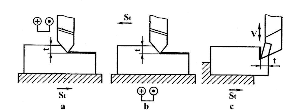
Fig. 6.13. Shaping (a), planing (b) and slotting (c)
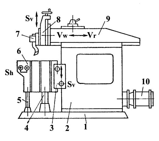
Fig. 6.14. Shaping machine: 1 – foundation plate; 2 - body; 3 – traverse for transference Sh
of the table 6 horizontally; 4 – column; 5 – screw for transference Sv of the table 6 vertically; 7 – tool;
8 – support; 9 - ram, doing horizontal motions: Vw – working stroke and Vr – return stroke; 10 – drive
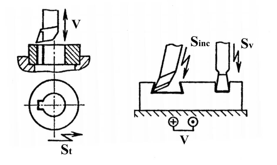
Fig. 6.15. Examples of jobs that can be done by the slotter
The planer is the largest of the reciprocating machine tools (Fig. 6.16). Since it is larger than the shaper and the miller, the planer can take work, which neither of those machines can handle. It is also capable of taking mach heavier cuts than either of those machines. The shaper moves a tool against the workpiece, but the planer moves the work against the tool. The work is mounted on a table, which is supported throughout its entire movement, so a maximum support is obtained. Like the shaper, the planer is intended to produce vertical, horizontal or inclined planes. It can also produce certain warped surfaces if these surfaces are composed of straight-line elements and the work can be indexed or turned. Modern planers have tables of up to 25...30 m in length.
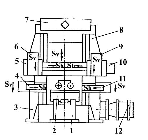
Fig. 6.16. Block diagram of a planer: 1 – body; 2 - table; 3, 8 – colomns; 4, 6, 9,11 - tool-heads;
5, 10 – traverses; 12 – drive
6.9. Milling
Milling is the metal cutting operation, in which chip is detached by series of cutting edges arranged on the circumference of rotary milling cutters. Due to the high number of cutting edges, a large volume of chip can be removed in the single operation. Frequently, the workpieces may be finished in the single operation.
Milling tool is a cutter, which rotates around either horizontal or vertical axis. In accordance with this there are two types of milling (horizontal and vertical one) and three types of milling machines: horizontal, vertical (Fig. 6.17) and universal. The latter machine has the spindle, which can incline. Two methods of horizontal milling are distinguished: cut-up (conventional) and down-cut (climb) milling (Fig. 6.18).
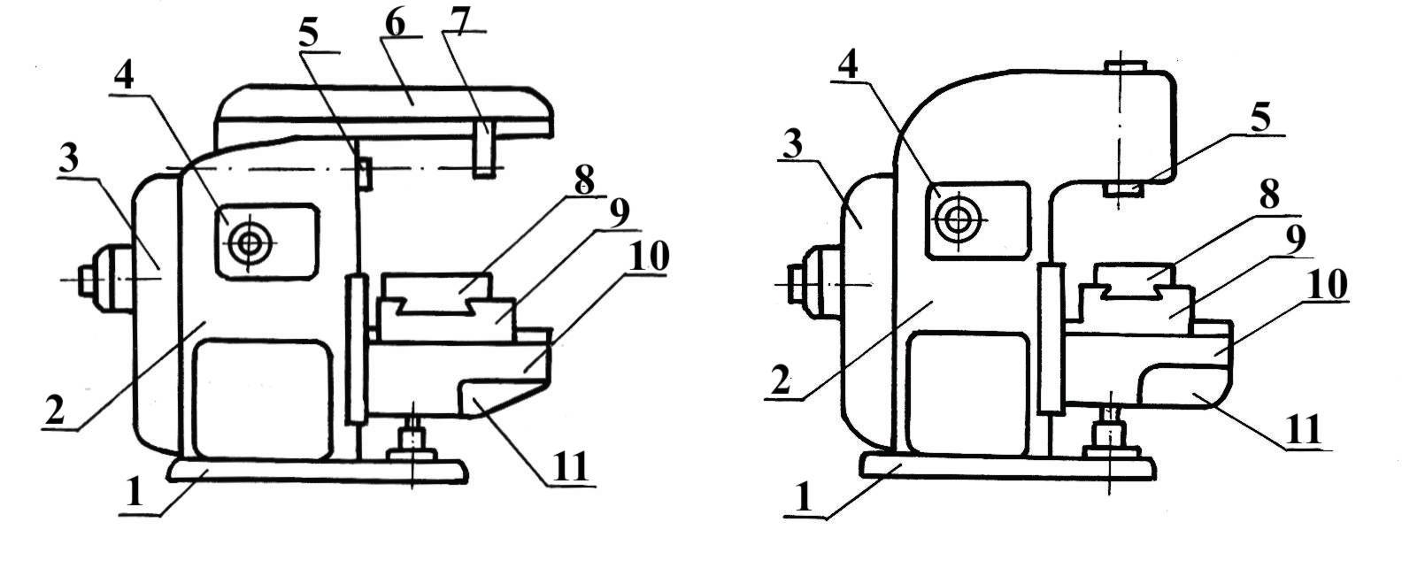
Fig. 6.17. Horizontal (a) and vertical (b) milling machines: 1-base; 2-column;
3-electric motor with belt transmission; 4-spindle speed gear box; 5-horizontal or vertical spindle;
6-overarm; 7-outer arbor support; 8-table; 9-slide; 10-knee; 11-feed gear box
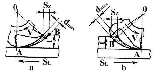
Fig. 6.18. Conventional (up) (a) and climb (down) (b) milling: thick-ness of removed metal;
dmax – maximum chip thickness; Sz – feed motion on one tooth of cutter
The milling cutters used in horizontal machines are called hobs. The longitudinal axis of the cutter runs in parallel to the surface of the workpiece to be milled. Teeth of the cutter penetrate into the material when cutter is rotated. In cut-up milling process (Fig. 6.18a) the cutter rotates (cutting motion V) against the direction of movement of the work (feed motion SL). The workpiece runs against the milling cutter. Each tooth or cutting edge of the cutter starts with zero chip thickness (point A) and increases it to maximum dmax as tooth leaves the work (point B). So, the load on the tooth increases gradually. But cutting forces aspire to lift the workpiece causing its vibration and deterioration of the machined surface. Nevertheless, cut-up milling method is the ordinary or conventional method used in horizontal milling machine work.
In the down-cut milling method (Fig.6.18b) the cutter revolves in the same direction as the work moves. This results in maximum chip thickness dmax at the beginning of the cut tapering off to zero thickness at the end of the cut and in high shocking loads on the teeth. Therefore, this method can be used only with particularly steady milling machines. The workpiece in this method is pressed to a table of the machine that results in high quality of surface finish.
Both in conventional and down-cut milling the cutting tool and machine are loaded not uniformly. This non-uniform stress may be balanced to a considerable extent by a special arrangement of the cutting edges of the cutter, e.g. in spiral teeth milling cutter (Fig. 6.19a).
Milling cutters for horizontal milling machines. Cylindrical milling cutters are primarily used for milling the plane surfaces (Fig.6.19a).
If both plane surfaces and end faces are to be milled at the same time shell-end cutters (Fig. 6.19c) are used (sometimes they are called corner cutters).
If the workpieces are to be slotted circular saw blades of the required width are used (Fig. 6.19q).
Angular cutters (Fig. 6.19i) are used to produce straight-sided shapes. To manufacture contoured surfaces or profiles formed milling cutters (Fig. 6.19k) of the appropriate shapes are used.
V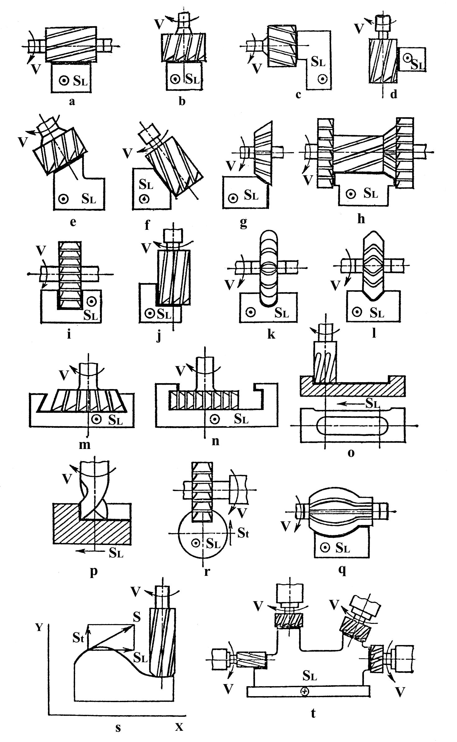
Fig. 6.19. Basic milling operation and tools
If surfaces of different dimensions or certain contours are to be produced on a workpiece, it is possible to use a set of milling cutters (gang cutters) (Fig. 6.19h) with a view to machining the workpiece in one single operation.
Basic operations and tools of vertical milling machines. The cutter, mounted in the work spindle of vertical milling machines, normally operates in a position perpendicular to the surface of the workpiece to be milled. The teeth of the cutter remove a uniformly thick chip. This results in more uniform stress on the milling machine. In vertical milling the cutter performs the cutting action with the teeth on the end face. Therefore, this cutting operation is also known as face milling (Fig. 6.19b). To mill grooves end (Fig. 6.19o) or side milling cutters are used; their width should be equal to that of the groove to be milled. In many cases milling by means of end milling cutters has the advantage over horizontal milling. Vertical milling machines are used to produce flat surfaces and are also employed to cut recesses of various type in work pieces.