

6.7. Drilling
6.7.1. Main Operations
There are several operations of holes machining that are usually done by a drilling machine.
Drilling is an operation of producing a circular hole by removing solid metal. The cutting tool used is called a drill. The drills are most commonly used in the machine shop are twist drills. Figure 6.7 shows such a drill with the main parts identified.
The drill has two (main) cutting edges and one crossing cutting edge. The dimensional accuracy of drilling (Fig. 6.8a) is not high.
Boring is the operation of enlarging a hole with a drill (Fig. 6.8b), or by means of a cutting tool with 3 and more cutting edges, named a bore (Fig. 6.8c), or by means of an adjustable cutting tool with only one cutting edge (Fig. 6.8d, e). The bore is similar to the drill, but without crossing cutting edge.
Reaming (Fig. 6.8 f) is an operation of sizing and finishing a hole by means of a cutting tool having several cutting edges. This tool is called a reamer. Reaming serves to make the hole smoother, straighter and more accurate.
Boring provides higher shape and dimensional accuracy than drilling.
Counterboring (Fig. 6.8 g) is an operation of enlarging the end of a hole cylindrically, as to produce recess for a fillister-head screw.
Countersinking (Fig. 6.8 h) is an operation of making of coneshaped enlargement on the end of a hole, as to make recess for a flathead screw.
Spot-facing (Fig. 6.8 i) is an operation of smoothing and squaring the surface around a hole, as for the seat for a nut or head of a cap screw.
Some bores have guide cylinder for getting an alignment of a drilled hole and cutting hole or surface.
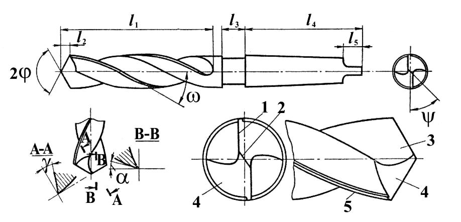
Fig. 6.7. Parts and elements of twist drill: l1 - body; l2 - lip; l3 - neck; l4-shank; l5 - tang;
1-main cutting edge; 2-cross cutting edge; 3-top rake; 4-back rake
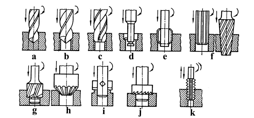
Fig. 6.8. Main operation of hole machining: a – drilling; b – boring; d, e – enlarging by cutting tools;
f – reaming; g – counterboring; h – countersinking; i, j – spot-facing; k – threading
Treading (tapping) (Fig. 6.8 k) is an operation of forming internal threads with a tool called a tap. To withdraw the tap by power in a drilling machine either a reversible motor or reversing attachment, or tapping attachment are required. To withdraw a tap by hand it is necessary to loosen the chuck or other holding device.
6.7.2. Drilling machines
Drilling is one of the oldest methods of tooling. Most different materials such as wood, metals, and plastics are drilled by means of appropriately shaped tools.
Drilling machines are primarily used for making and treating the cylindrical holes. Drilling and other operations frequently serve to prepare metal parts for riveting, bolting, pinning and other operations.
In metal working the bench-type (Fig.6.9), upright (Fig.6.10), radial (Fig.6.11) drilling machines, boring and fine boring (Fig. 6.12) machines are used.
The drilling spindle 1 of bench type machine can be moved vertically up and down by manual control 2. The cone pulley 3 of the drilling spindle is connected with a cone pulley 4 of an electric motor 5 by a belt. Normally three-step cone pulleys are used. Thus, a range of three speeds is obtained, which are selected by shifting the belt onto the various steps of the cone pulleys. A tool holding device 6 is fitted on the lower end of the drilling spindle. The column 7 is fitted on the cast-iron bed 8.
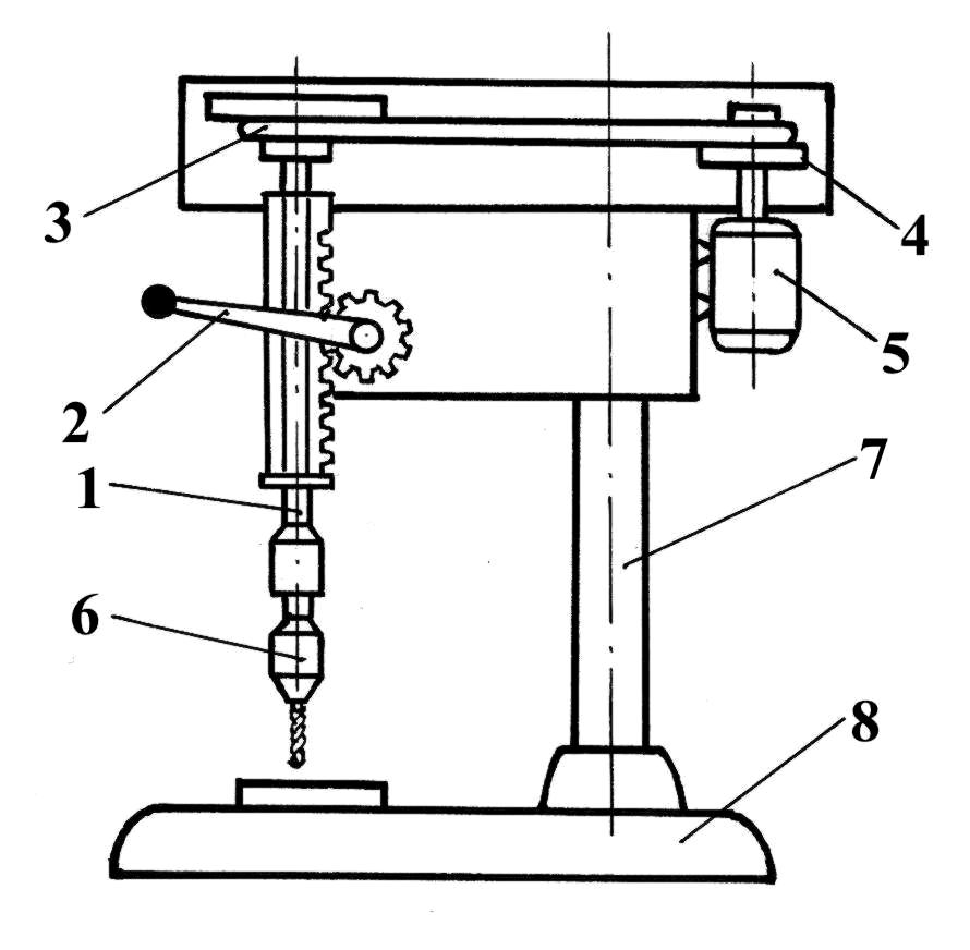
Fig. 6.9. Bench-type drilling machine: 1 – sprindle; 2 – handle; 3, 4 – cone pulleys of V-belt transmission;
5 – electric motor; 6 – chuck with drill; 7 – column; 8 – bed
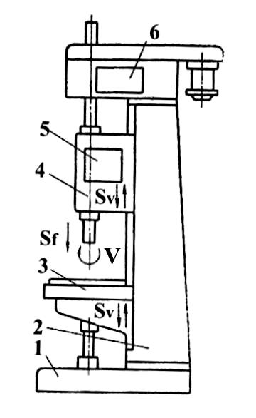
Fig. 6.10. Upright drilling machine: 1 bed; 2 – column; 3 – table; 4 – spindle; 5 – feed gear box;
6 – speed gear box; V – spindle (tool) revolution; Sf – feed motion;
Sv – vertical motion of table 3 and feed gear box 5
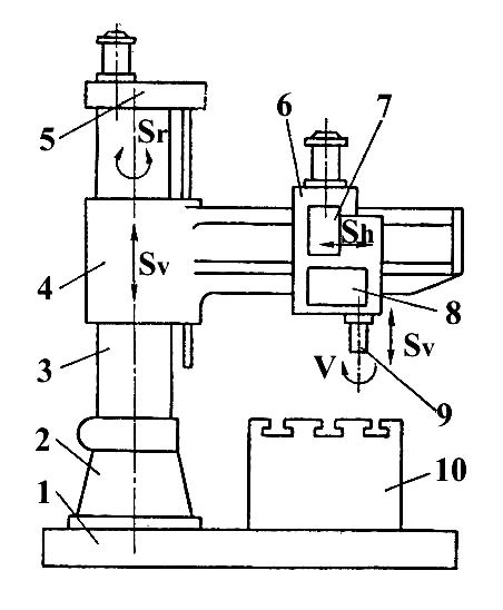
Fig. 6.11. Radial drilling machine: 1 – plate; 2 – bed; 3 – rotating (Sr) column;
4 – rotating together with column and moving up and down (Sv) traverse; 5 – moving mechanism;
6 – spindle head, moving horizontally (Sh); 7 – gear box of springle head; 8 – feed mechanism;
9 – spindle; 10 – table
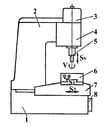
Fig. 6.12. Fine boring machine: 1-bed; 2-frame; 3-drive; 4-boring head; 5-spindle; 6-table; 7-carriage; 8-drive
The design of upright drilling machines (Fig. 6.10) in essence resembles that of a bench type drilling machine. Modern upright drilling machines, however, are not driven by means of a belt drive. The gearcase 6 houses several pairs of gears, which can be engaged by appropriate shifting levers. In this way a wide speed range is ensured (more than 30 speeds).
If material is hard or drills of a large diameter are used, the manual power by means of hand lever will not suffice to perform the feed motion Sf. Therefore, upright drilling machines are equipped with feed-gear mechanism 5 which can be thrown into gear when required. From this follows that there are two possibilities of feeding the drilling spindle 4 (Fig. 6.10). First, the spindle can be fed manually with the feed-gear mechanism disengaged. Secondly, the required feed motion from motor through gearcase 6 and spindle 4 can be effected by means of the feed-gear mechanism 5. The feed-gear mechanism together with spindle, tool and table 3 can move vertically up and down (Sv) along slide bars.
For large workpieces, or workpieces, which require very precise holes, radial drilling machines or jig boring machines are used.
The design of the radial drilling machine (Fig.6.11) in essence resembles that of the upright drilling machine, but its spindle, except vertical Sv, can do two horizontal motions by rotation column 3 Sv and horizontal replacement of spindle head 6 Sh on the traverse 4. The part to be worked up is fixed on the table 10 or on the plate 1.
The fine-boring machine (Fig. 6.12) has spindle 5, which can do two motions: rotating V and vertical Sv ones. The machine has a table, which can do two horizontal motion: S1 (perpendicular to the drawing plane) and S2 (parallel to the drawing plane) with very high accuracy (0.001 mm). The highest accuracy in operation of these machines is achieved by means of
- high accuracy of transference mechanism of table;
- holding constant temperature (20 ± 1 °C);
- sometimes using diamond tools.
Except vertical drilling machines there are horizontal drilling and boring machines of different types.