

4.3. Technological Plasticity
Technological plasticity is the main property required for metal forming processes. The plasticity of metals depends on:
- alloy composition and its structure;
- working temperature;
- scheme of deformation;
- rate of deformation.
Pure metals possess higher plasticity than their alloys. The less carbon contents, the higher is the plasticity of steel. When temperature increases the resistance of metal to deformation decreases, because of decrease in strength and hardness.
In every point of stressed body elementary very small cube may be picked out so, that plane stresses should be perpendicular to its plane surfaces. There are 9 cases of stressed states with one, two and three main stresses (Fig. 4.5). An alloy has higher plasticity when it undergoes compressing stresses and it has lower plasticity in case of tensile stresses.
The degree of deformation at first decreases, then raises with the increase in deformation rate.
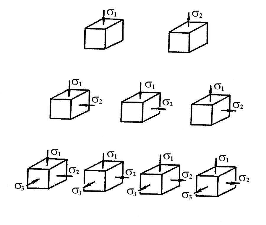
Fig. 4.5. Possible cases of stressed state
4.4. Heating of Metals
There are three types of metal forming with respect to work temperature: cold forming, thermomechanical treatment and hot forming. The main type is hot forming, or hot plastic metal working. As we know, cold metal working causes strain hardening (sometimes it's favourable effect), decrease in plasticity and, as a result, cracks in billets appear. During hot plastic working metal has high plasticity, it does not undergo structural changes and strain hardening, capacity of forming machines and deformation forces required are less as compared with cold forming. But hot forming causes a scale formation, which leads to metal losses and dimensional accuracy decrease.
Heating temperatures for steel are (Fig. 4.6) by 100…200°C below solidus line AE and by 25…50°C above the line GSK, that is hot forming is carried out when steel has homogeneus austenite structure (hypereutectoid steel has structure: austenite + carbides).
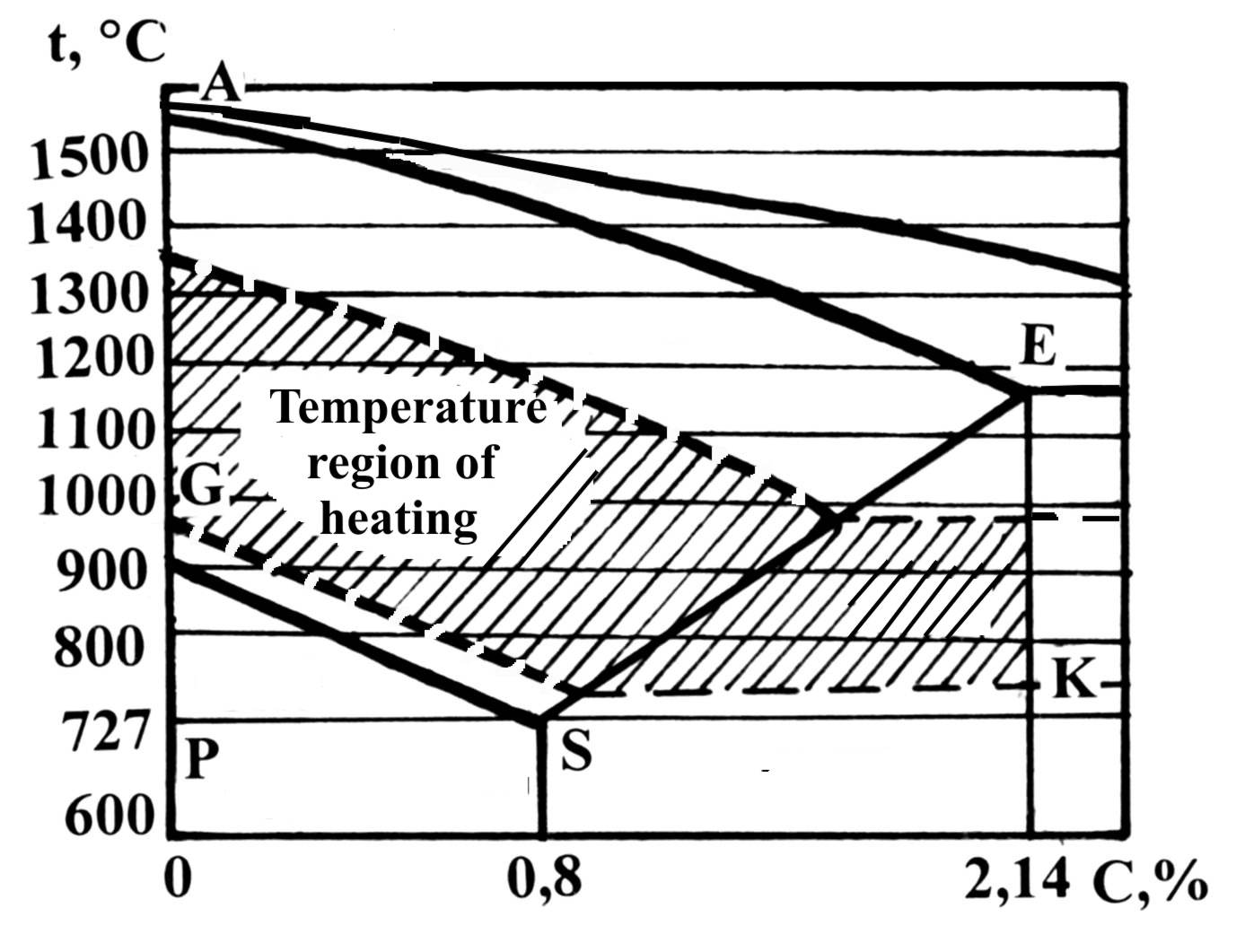
Fig. 4.6. Heating temperatures for hot plastic metal working
According to a source of heat a distinction is made between flame (gas or oil) reverberatory furnaces and electrical resistance reverberatory furnaces. According to a working principle a distinction is made between bath and continuous furnaces (Fig. 4.7).
Flame furnaces are used for big ingots, both electrical induction and contact heating devices are used for small billets.
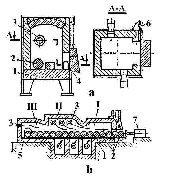
Fig. 4.7. Chamber (bath) (a) and continuous (b) heating furnaces: 1 – bottom; 2 – billet; 3 – gas burner;
4 – lid; 5 – unload hole; 6 – flue; 7 – pusher; I – preheating zone (600…800C);
II – zone of maximum heating (1250…1350C); III – Standing zone (1200…1300C)
4.5. Rolling
Rolling is the main method of metal forming. Bars, pipes, double tees, corners, sheets, balls, wheels and other products are manufactured using this method. Rolling is a method, in which revolving rolls are used for deformation of material.
A distinction is made between three rolling methods (Fig. 4.8): lengthwise (a), cross (b) and helical (c).
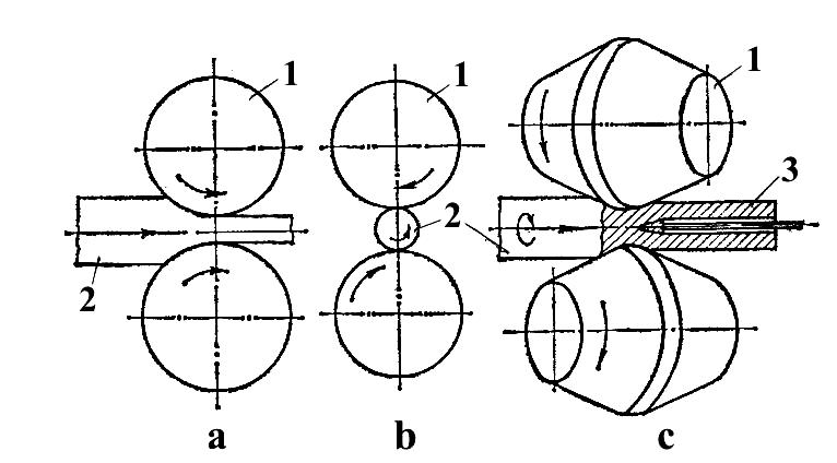
Fig. 4.8. The main methods of rolling: 1-roll; 2-billet; 3-mandrel
Let us consider the lengthwise rolling (Fig. 4.9). Sizes of a billet before rolling: L, B, H; after it 1, b, h, and L<1, B<b, H>h.
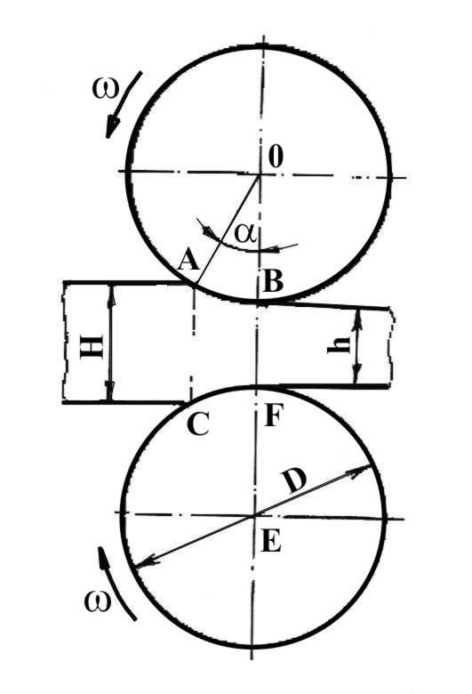
Fig. 4.9. Deformation of a billet in lengthwise rolling
Degree of deformation in general named drawing (extension) coefficient:
![]() (4.5)
(4.5)
Four main types of the rolled stock (products) are known:
- shape rolled stock;
- sheet rolled stock;
- pipe (tube) rolled stock;
- special rolled stock (periodical, balls, wheels and so on).
Tools and Equipment for Rolling. Metal is deformed between rolls, which may be plain (Fig. 4.10a) or size (Fig. 4.10 d), i.e. with grooves on their surfaces. Two grooves of size rolls form a roll pass. The pass may be open (fig 4.10 b) or closed (Fig. 4.10 c).
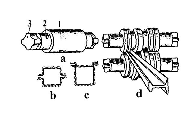
Fig. 4.10. Milling rolls and passes: 1 – barrel; 2 – neck; 3 – capture
Equipment for rolling is named a mill (Fig. 4.11).
According to the number and arrangement of roll stands, a distinction is made between: duo mill; three-high mil; double duo mill, or four-high mill; multiroll mill; universal mill.
Rolling technology. Duo rolling mills, as a rule, are used to manufacture half-finished products: blooms and slabs. The mill, named blooming, is used for squeezing of ingots to obtain blooms with cross section from 150x150 to 450x450 mm. Then blooms are used for production shape rolled stock. The mill named slabing is used to produce slabs, which have cross section form 65x1600 to 300x2600 mm and then are used for sheet rolled stock manufacture.
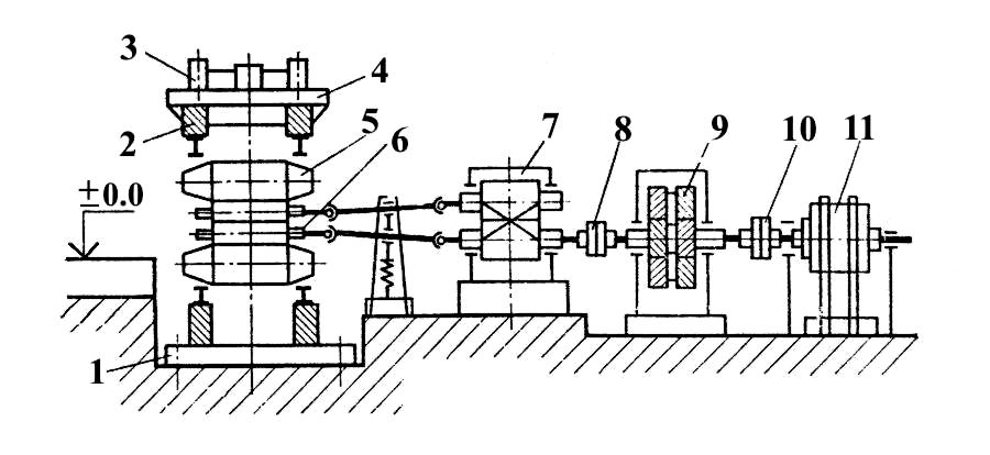
Fig. 4.11. Scheme of a mill: 1-bed of roll stand; 2-4-pressing device; 5,6-support and working rolls;
7-pinion stand; 8,10-clutch; 9-reduction gear; 11- electrical motor
Three-high mill has two passes and works similar to duo mill.
Double duo and multiroll mills provide the use of working rolls with small diameter, and by this to reduce deformation zone volume without bending of the rolls.
To receive a required cross section of rolled product bloom or slab is passed through systems of passes (Fig.4.12).
Welding pipes are produced from skelp (Fig. 4.13). Process includes forming of plane half finished article (skelp) in a pipe, welding and finishing operations. Skelp is deformed at temperature 1300…1500°C and thereby furnace welding is mainly employed. Electric arc welding also may be used.
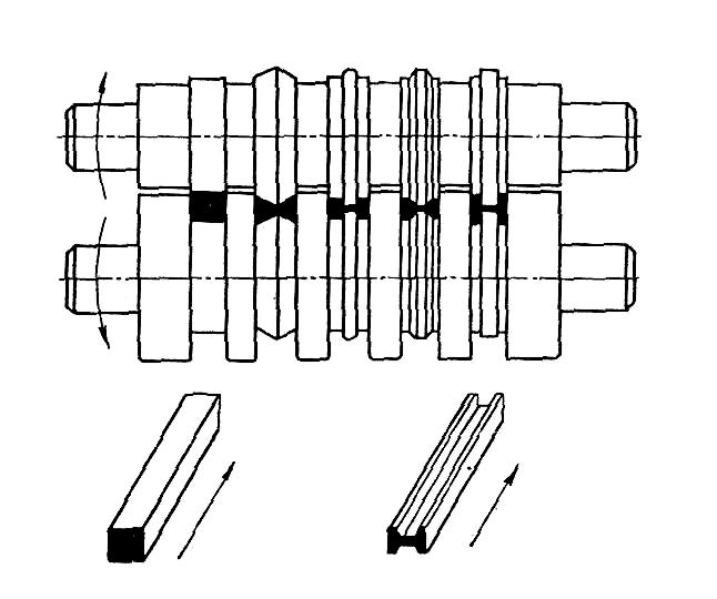
Fig. 4.12. Production of double-tee bar
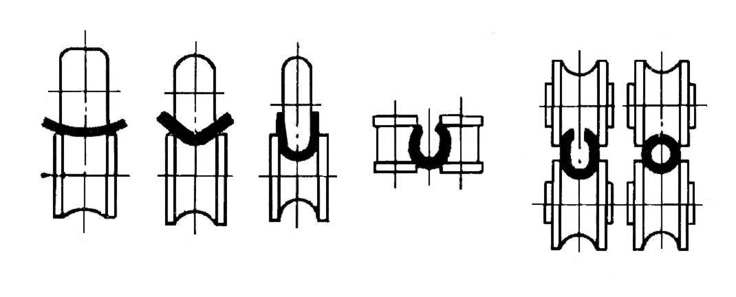
Fig. 4.13. Process of welding pipes production