

3.5. Centrifugal Casting (Spinning)
This method is used to manufacture hollow castings, which have a shape of rotating bodies. Two modifications of the method are distinguished: with vertical and horizontal axes of rotation (Fig. 3.13).
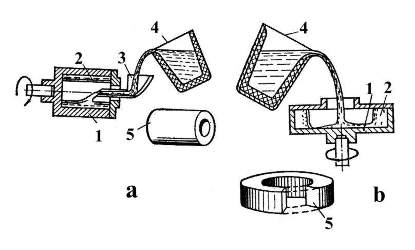
Fig. 3.13. Centrifugal casting with horizontal (a) and vertical(b) axes of rotation:
1 – mould; 2 – liquid metal; 3 – spout; 4 – ladle; 5 – casting
Ingot moulds are made of cast iron. They are heated (150...450°C) and painted by refractory mixture (paint) before pouring of metal.
Method with vertical axis of rotation is used for production of castings small in height, because inner surface of the casting acquires paraboloid shape and lower diameter of hollow is less than upper one.
The second method is used for castings of significant length production, e.g. hydrostatic pressure and overflow pipes. They have length from 3 to 12 meters. Advantages of the methods:
- high density of metal due to the action of centrifugal forces;
- reduced metal consumption, because a gating system is absent;
- inner hollow in castings is received without using of cores;
- a mould is easily filled by molten metal under the action of centrifugal forces;
- a patternless method.
The disadvantages are as follows:
- low dimensional accuracy of inner surface;
- inner surface is contaminated by segregation products and non-metallic inclusions.
3.6. Pressure-Die Casting
Method has the highest output from 200 to 400 castings per hour. Sand mixtures are not applicable for the method. Crystallization of castings is carried out in a metal mould, named press-mould. Essence (main point) of the method is that liquid or both liquid and solid metal is pressed into press-mould under high pressure (30...300 MPa) and with high speed (0.5...140 m/sec). Mass of castings may be from a few grams to several tens kilograms. Alloys of zinc (very often), aluminium (often), magnesium (often), copper (sometimes), iron (very seldom) base are used.
The casting's nomenclature ranges from part of a zipper to automobile block of cylinders.
Automatic or semi-automatic plunger machines with cold and hot pressing chambers are employed (Fig. 3.14).
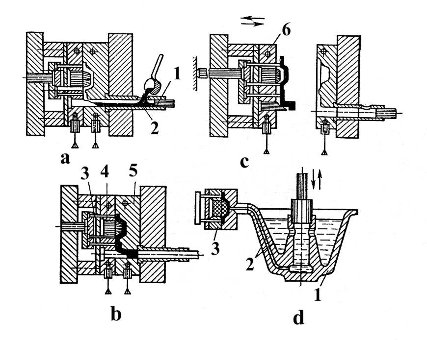
Fig. 3.14. Plunger machines with cold (a, b, c) and hot (d) pressing chambers: a…c:
1- plunger; 2 – pressing chamber; 3 – pusher; 4 – metallic core; 5 – removable half-mould;
6 – irremovable half-mould; d: 1 – heating crucible; 2 – metal-conductor; 3 – press-mould
In the first type machine the metal together with air by a plunger 1 is pressed into mould 2 and solidifies under pressure. Compressed gases dissolve in metal and the casting acquires normal density. But further heat-treatment is not available, because gas holes are formed at high temperature.
In the second type machine the metal is pressed into a mould 3 without any gases, but plunger and chamber work at high temperature, in liquid metal and by this reason they are rapidly damaged.
The advantages of the method:
- very high productivity;
- sand mixture isn't used at all;
- dimensional accuracy is very high (for example, screw thread may be received);
- thickness of casting may be 1 mm and less;
- patternless method.
The disadvantages of pressure die-casting:
- high cost of press-moulds;
- short service life of press-moulds;
- powerful machines are required to produce medium mass castings.