

3.2. Manufacture of Castings in Sand Moulds
This is a main foundry method. About 70 % of castings are produced in sand moulds. There are main technical operations involved in making castings in sand moulds:
- development of casting's drawing, using a drawing of the part (article) and working out of technological process;
- patternmaking, including core boxes, gating system patterns, moulding boxes (flasks) and other auxiliary equipment;
- preparation of moulding and core sands;
- moulding (manufacture of mould and cores);
- melting an alloy and pouring it into the mould;
- cooling of moulds and shaking out of castings;
- cleaning of castings to remove moulding and core sands;
- cutting off the gating system, risers and fins;
- preliminary inspection of the casting to reveal defects and assess general quality;
- heat-treatment;
- fettling of castings to remove scale (rust);
- final inspection (structure, mechanical properties, etc);
- finishing operations (painting, oiling, branding, etc);
- shipment.
Development of casting's drawing (elaboration of technological process) consists of several steps.
First step is examination of the drawing of a part to be cast (Fig. 3.4 a):
- surfaces A, B and C must be machined;
- D is a hole with screw, which can't be produced by a foundry process;
- ring flute B must be done by machine tool;
- lower part of the article C has higher surface quality than upper one;
- internal surface E does not undergo to machining.
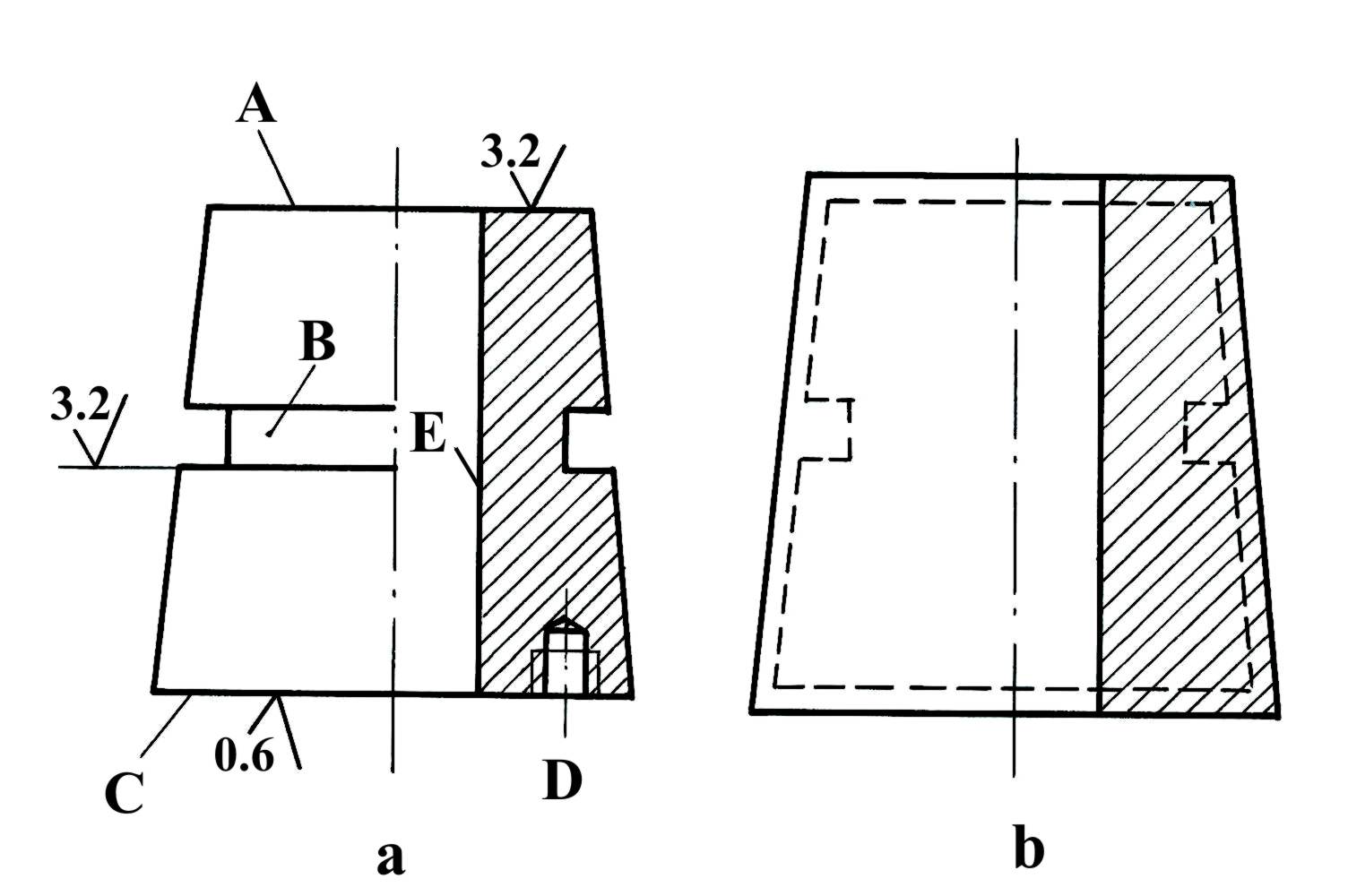
Fig. 3.4. Drawing of a part to be cast (a) and casting (b)
Next step is to select the position of the casting in the mould so as to ensure directional solidification from the casting towards the riser located above the feed end.
We can choose two possible positions of the casting in the mould (Fig. 3.5): with vertical (a) and horizontal (b) axis.
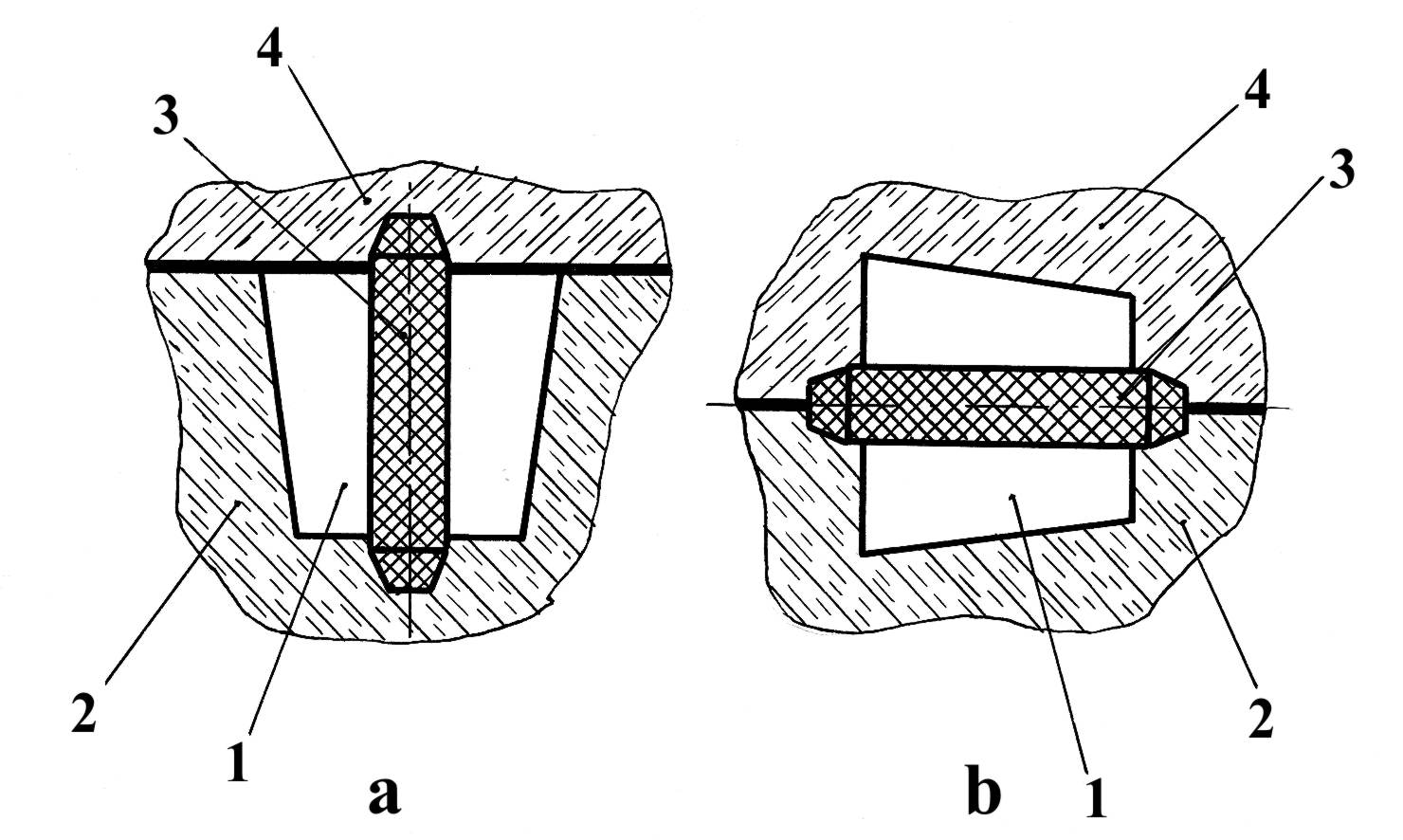
Fig. 3.5. Possible location of the casting in the mould: vertical (a) and horizontal (b) positions;
1 – mould cavity (casting); 2 – lower half-mould; 3 – core; 4 – upper half-mould
Let us admit that our alloy possesses small linear shrinkage, so we should not use a riser and, hence, opt for the second position which provides equal distribution of metal in half-moulds.
The next step: we see that surfaces A, B, C, D have to undergo machine tool operations. Proceeding from this we ought to specify reference book indices: machining allowance; overlaps (flute B and holes D are not available to be produced as-cast, they are formed by turning and drilling); foundry slopes to ensure the pattern to be removed from the mould (slopes are normally equal to 1...3°).
Then, using reference book, we have to calculate sizes of gating system, i.e. set of channels, to feed molten metal into the mould cavity (Fig. 3.6): a pouring basin (cup) 1, a downgate 2, a dirt trap (crossgate) 3, ingates 4.
Patternmaking. A pattern serves for receiving of hole (cavity) of definite shape in the mould i.e. to make an imprint in the mould that conforms to the shape of the casting to be made. Thus, the shape of a pattern supposes to accommodate the casting's shape. Patterns are made of wood in small scale (individual) production and of metal and plastics in mass production of castings.
According to the selected technology we have to manufacture the pattern consisted of two parts or split pattern (Fig. 3.7). Pattern's dimensions are in excess of casting's ones by shrinkage value. Gating system patterns are needed to make in the mould cast channels for feeding mould cavity by liquid metal. Then core box is made (consists) of two parts (in our case). Flasks are intended to hold the mould and are also prepared.
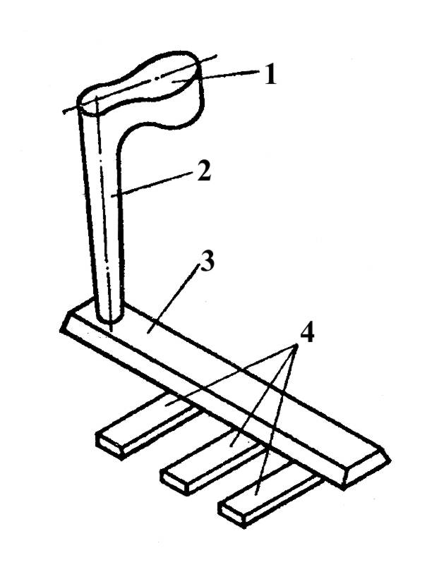
Fig. 3.6. Gating system: 1 – pouring basing; 2 – downgate; 3 – crossgate; 4 – ingates
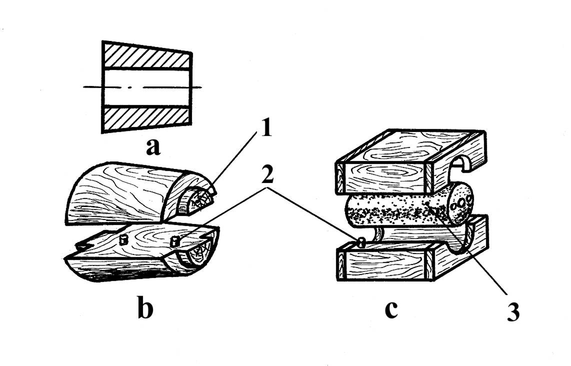
Fig. 3.7. Casting (a), pattern (b) and core box (c): 1-core print; 2-slotted key; 3-core
Preparation of moulding and core sands. Mould and core sands (mixtures) consist of:
- fireproof base (silica sand SiO2, alumina A12O3, chromite Cr2O3, powders of magnesite, chromomagnesite and so on);
- binder: fireproof clay which is hydrated silicate of alumina: Al2O3·2SiO2·2H2O (caolinite) or Al2O3·4SiO2·H2O (bentonite); water glass Na2O·mSiO2 or K2O·nSiO2; dextrine; molasses; vegetable oils; sinthetic resins;
- technological additions (water, graphite powder, mineral oils, wood sawdust and others).
Classical, widely used and the cheapest moulding sand consists of: 6...10% fireclay, 4...6% H2O, SiO2-rest.
Owing to hindering properties of fireclay (or another binder) the sand grains are connected with each other, thus imparting strength to the mixture. Due to pores (pockets) between grains the mixture possesses gas permeability (gases can pass through the sand). The more binder contents the lower gas permeability of the mould mixture.
The following foundry terms are used. Green sand is the sand in the green, or undried condition. Casting into green sand or undried moulds is common practice for the majority of small-and medium-sized ferrous and non-ferrous castings.
Dry sand is sand from which all the free, or uncombined moisture has been removed by heating in a drying oven or stove.
Facing sand is used in green state against the face of the pattern and forms the face of the mould. It is of high quality.
Backing or floor sand is sand from cast-up moulds, it is used several times to fill the flask over the facing layer.
Facing and backing sands are used in individual production. In mass production, (machine moulding) unit sand is used. It has a high quality (similar to the facing sand).
Core sand is used for cores manufacture to produce hollow castings. Core sand is usually used as dry sand because core is surrounded by molten metal. For compliance (deformability) of cores during solidification and shrinkage of castings the wood powder (sawdust) is used.
Mould and core sands are prepared by special equipment: edge-runner mills, aerators, hoppers, conveyors and others.
Main operation of mould and core sands preparation is mixing of the components.
Moulding. Let us consider the moulding process step by step (Fig. 3.8).
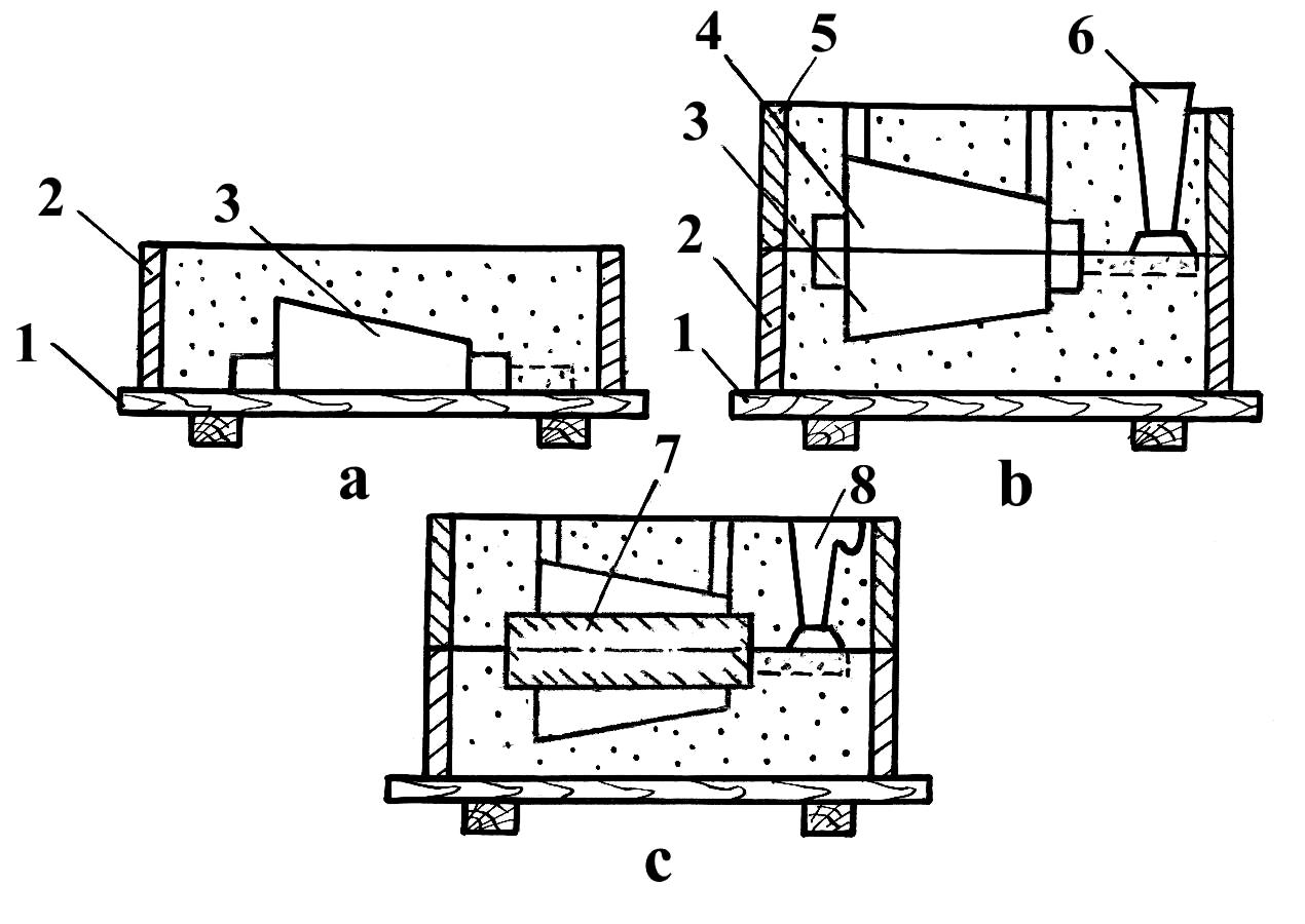
Fig. 3.8. Moulding process: a-drag moulding; b-cope moulding; c-assembled mould:
1 –board; 2, 5 – flasks; 3,4 – parts of a pattern; 6 – gating system pattern; 7 – core; 8 – gating system
A ramming-up board 1 is placed on a table, and lower part of a pattern 3 and a flask 2 are placed on the board. Then pattern is covered by facing sand and by backing sand. Facing and baking sands are rammed by hand or pheumatic rammer.
After ramming of sand the superfluous mixture is removed by a ruler, drag is turned over and the second part of the pattern 4, gating system patterns 6 and the next flask 5 are mounted. The flask is filled up by facing and backing sand and rammed.
So the upper part of the mould (cope) is prepared. Then the cope is lifted and parts of the pattern are removed from the half-moulds. The foundry slopes enable to remove patterns without the mould's damage.
Cores are made similar to the mould. The mould assembly consists of installation of core 7, mounting the cope, fastening the half-moulds by clamps or loading them by pouring weight. Clamps and pouring weight prevent lifting of the cope by liquid metal.
Sand moulds and cores are used one time. After pouring and crystallization of the casting the mould is destroyed by shaking out operation. Shaking out of castings is carried out using pneumatic knock-out (individual production) or jolting knock-out grid (mass production) (Fig. 3.9).
Cutting off the gating systems, risers and fins are carried out by hammers, mechanical saws, pneumatic or hydraulic presses. Fins are removed by pneumatic chisels or by grinding machines.
After inspection to reveal defects, chemical analysis and mechanical tests the required heat-treatment is conducted. Next operation is fettling of castings to remove burning-on scale and oxide films from the casting's surface. This work is carried out by shot blasting (blast cleaning), hydroblasting and tumbling (rumbling).
Finally inspection (visual, pressure test, X-ray screening, etc.), finishing operations (painting, branding, etc) and shipment are performed.
Up to 70...75% of castings are produced in sand moulds. Hence, this is the main casting method. Its advantages were listed in section 3.1.
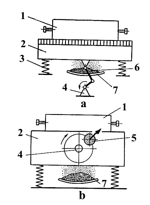
Fig. 3.9. Off centre (a) and inertion (b) jolting knok-out grids:
1-mould; 2-grid; 3-spring; 4-drive; 5-inertion load; 6-sand; 7-sand-trap
The disadvantages of sand mould casting are as follows:
- moulds and cores are used one time;
- still relatively high manual labor consumption and environment pollution (dust, evaporations);
- low dimensional accuracy of castings and respectively high machining allowances.
To avoid these disadvantages the special methods of castings have been proposed.