

Equipment, instrument, materials
Hydraulic press with the nominal force of 0.62 MN 1
Laboratory drawing mill with the
pulling force of 4000 N 1
Pneumatic hammer with the mass of
falling parts of 50 kg 1
Technological equipment for direct pressing of
lead cylindric rods 5 mm in diameter
(container's diameter is 26 mm) 1
Set of reducing dies with the calibrative
orifice diameter of 3.1; 3.2; 3.3 mm 1
Dimension gage 5...6
Aluminium wire 3.5 mm in diameter,
10 m in length 5...6
Specimens of lead 25 mm in diameter
50 mm in length 5...6
Specimens of lead 30 mm in diameter
50 mm in length 5...6
The work must be executed as follows: Make acquaintance with the design and operational principle of equipment employed in pressing, drawing and forging.
Determine technological pressing force and deformation degree as a function of container, die and product (rod) diameter.
Press the round product of a given diameter.
Draw the aluminium wire through orifice (3.1…3.3 mm in diameter). Drawing force must be measured according to disposed on the mill indicator's readings and calibrative graph. Gage wire dimensions before and after deformation.
Determine deformation degree for each test and compare the values obtained with the permissible values for correspondent kind of metal forming. Plot the graphical dependences of drawing force upon deformation degree.
Fill the results in the form (table 4.1).
4.1 Results of the tests
Metal forming kind |
Material of a billet |
Dimensions of a billet, mm |
Extension coefficient, upsetting,% |
Redu-ction coef-ficient, % |
Force of deformation, kN |
||
before defor-mation |
after defor-mation |
Calcu-lated |
Deter-mined by test |
||||
Pressing |
|
|
|
|
|
|
|
Drawing |
|
|
|
|
|
|
|
Forging |
|
|
|
|
|
|
|
Contents of the report. Describe briefly the essence of pressing, drawing and forging processes (accompany the descriptions with required skethes), equipment employed. Characterize external appearance and quality of finished products. Present the formulas for deformation degree and technological forces determination in pressing, drawing and forging.
Present the filled testing form (table 4.1). Depict the effect of deformation degree on drawing forces and give necessary explanations.
4.2 Die forging of metals
Purpose of the work. To study a die forging process, a procedure of forging's draught development; make acquaintance with design and operation of crank press.
Theory. Die forging process has found a wide use in custom-made production of half-finished articles and provides forgings of high quality, favorable microstructure and minimal stocks allowed for machining to be manufactured. Die forging is a technological process of metal working, in which deforming and flow of a metal is carried out in special tools cal1ed dies.
Working surfaces of a die form close cavity which conforms in shape and sizes to the desired forging. The cavity is called an impression. Open and close impressions are distinguished in accordance with the character of metal flow during forging. In open impressions a clearance between die parts (top and drag) allows a metal to flow through it, facilitating, therefore, filling up of the impression and withdrawal of surplus metal (fin). In close impression, on the contrary, small clearance doesn't permit metal outflow from a die and, consequently, fin formation.
Forgings of a simple shape are usually stamped in dies with a single impression. Manufacture of intricate forgings in such dies is considered to be injudicious, because a lot of metal is wasted for fins and impression wears out rapidly. Intricate forgings are manufactured by sequential deforming of a billet in several impressions, thus, gradually approaching the required shape. Preliminary forming is carried out in preparatory impressions (upsetting, extending, bending etc). Finishing forming, correspondently, – in blacking and finishing impressions.
All the impressions are usually disposed in one die (Fig. 4.5). Application of preparatory impressions and sequence of their employment is determined during the design of forging technological process and based on forging's shape and sizes. Draught of a forging is developed in accordance with draught of an article (finished product), accounting stocks allowed for machining, technological biases, curvature radiuses, imprints of openings etc. It is for a designer to pick out a joint plane (face) of a die; to set up the stocks allowed for machining, technological biases, curvature radiuses and, if necessary, to provide imprints of orifices for subsequent piercing; to introduce corrections for machining convenience. The draught development procedure is presented in Fig. 4.6.
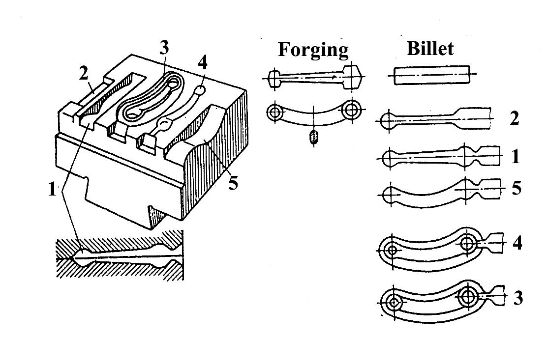
Fig. 4.5. Draught of a forging, die, multiple-impression die and sequence of operations, carried out in the die (2-1-5-4-3). Impressions: 1 – rolling; 2 – extending (fuller); 3 – finishing; 4 – blacking; 5 – bending
Volume of a billet is determined by dimensions of a forging:
Vb = Vf +Vfin+Vl+Vw
where Vf is volume of a forging;
Vfin is volume of fins, equals (0.05…0.25)Vf;
Vl is metal losses while heating, equals (0.5…0.8)% Vf for electric heating; (1.6…2.0)% Vf for flame heating;
Vw is wastes of metal.
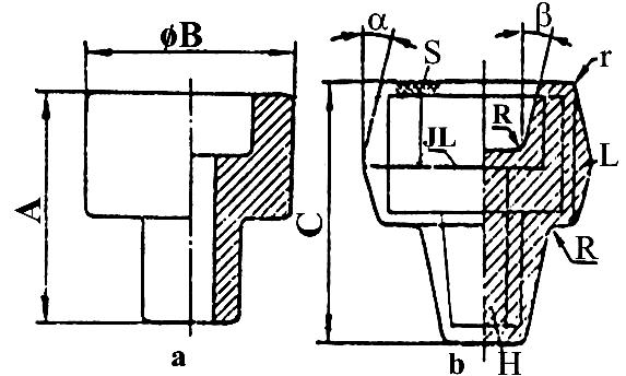
Fig. 4.6. Draught of the article (a) and the forging (b); S – stock, allowed for machining; L – overlap; a and b – stamping biases; JL-joint line; R; r – curvature radiuses; A, B- dimensions of the article; C – dimension of the forging
There are several types of equipment used for die forging, distinguished by the design and operational principle. Option is determined by sizes and shape of forgings, total output, technological and mechanical properties of working metal, automation requirements, convenience of operation, quality of finished products etc.
Steam-air hammers with the mass of fallen parts of 630…25000 kg are used for stamping of rather shaped forgings (0.5…200 kg).
Crank hot-forging press with the nominal force of 6.3…160 MN is the most advanced forging machine, differed favorably with high productivity, quality of forgings, small stocks allowed for machining and other advantages. The main units of this machine are following (Fig. 4.7): drive, principal executive mechanism and control system. Principal executive mechanism (crank mechanism) consists of crankshaft 9, coupler 10 and slider 1. Drive consists of electric motor 4, belt transmission 3, idler shaft 5 and gears 6, 7. The electric motor is turned on and shut down by means of clutch 8 and brake 2. Wedge 12 enables table 11 of the press to move vertically, providing adjustment of a clearance between top and bottom (drag) dies.
Dimensions of die forging equipment are selected to meet the deforming force (presses) or the work required for deformation (hammers).
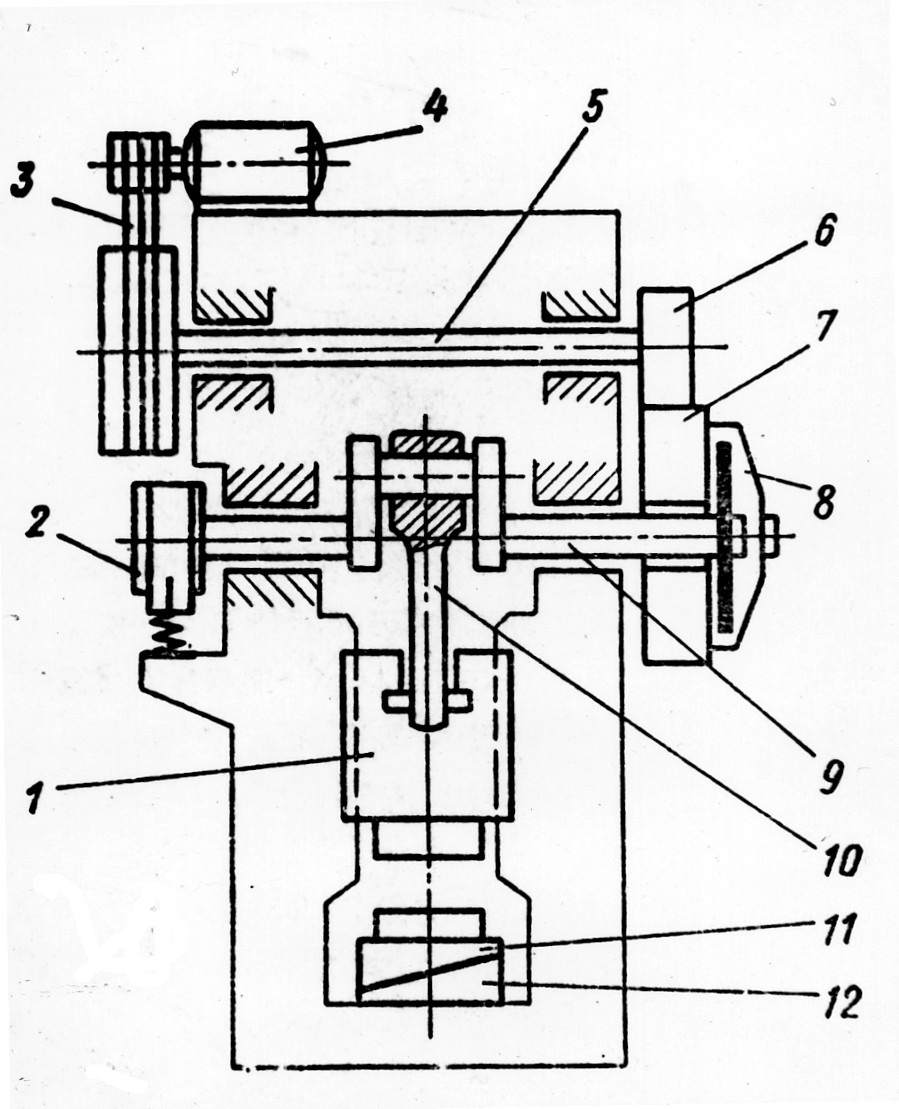
Fig. 4.7. Kinematics scheme of a crank hot-forging press: 1- plunger; 2 – brake; 3 – belt transmission; 4 – electric motor; 5 – shaft; 6 – gear; 7 – gear; 8 – mufticoupling; 9 – crank-shaft; 10 – lever; 11 – table of variable height; 12 – bas of the table