

Caution
If the inner tune is badly bent or creased, replace it. Excessive bending, followed by subsequent straightening, can weaken the inner tube.
Temporarily assemble the inner and outer tubes, and pump them back and forth manually to check for smooth operation.
If you feel binding or catching, the inner and outer tubes must be replaced.
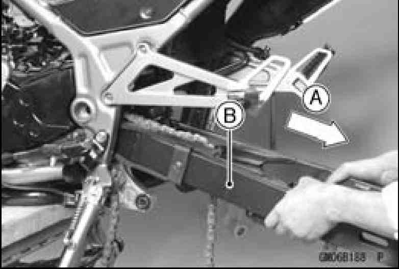
A straightened inner or outer fork tube [B] may fail in use, possibly, causing an accident. Replace a badly bent or damaged inner or outer tube, and inspect the other tube carefully before reusing it.
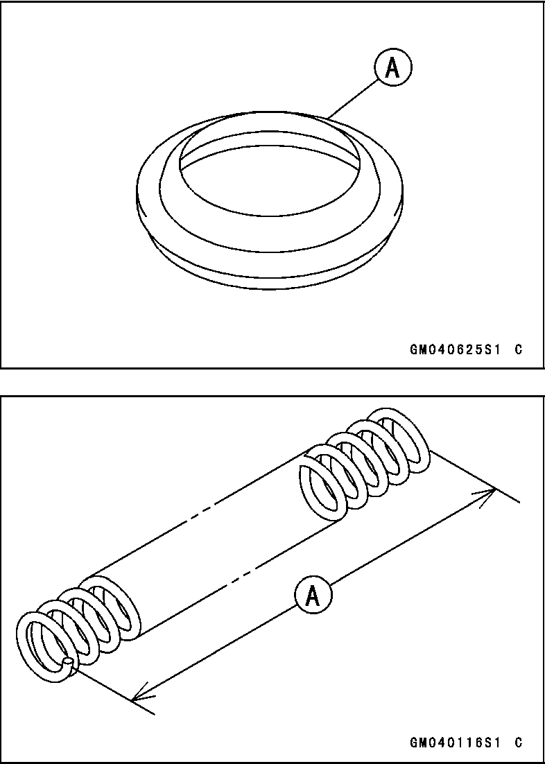
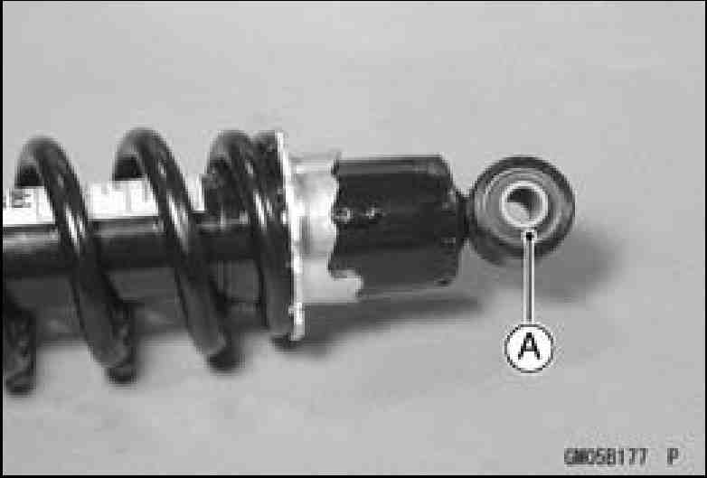
Inspect the dust seal [A] for any signs of deterioration or damage.
Replace them if necessary.
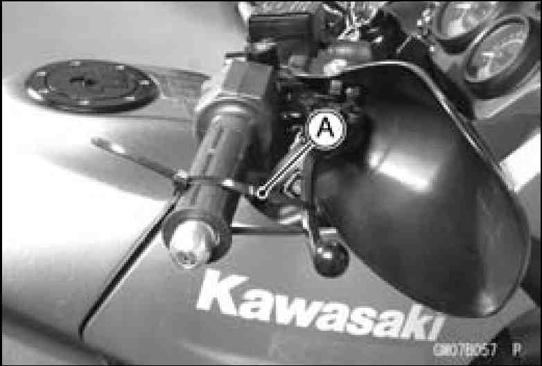
Spring Tension
Since the spring becomes shorter as it weakens, check its free length [A] to determine its condition.
If the spring of either fork leg is shorter than the service limit, it must be replaced.
If the length of a replacement spring and that of the remaining spring vary greatly, the remaining spring should also be replaced in order to keep the fork legs balanced for motorcycle stability.
Spring Free Length Standard: 522.5 mm (20.57 in.)
Service Limit: 512 mm (20.16 in.)
SUSPENSION 13-13 Rear Shock Absorber
The spring preload adjuster on the rear shock absorber has 5 positions so that the spring tension can be adjusted for different road and loading conditions.
• Using the hook wrench [A], turn the adjuster to adjust the spring tension.
Spacial Tool - Hook Wrench: 57001-1101
OThe standard adjuster position for an average-build rider of 68 kg (150 lb) with no passenger and no accessories is 2nd step from the weakest position.
• If the spring action feels too soft or too stiff, adjust it in accordance with the following table.
Spring Preload Adjustment
Position |
Spring Force |
Setting |
Load |
Road |
Speed |
1 |
Strong t ¦ 4 Weak |
Soft t ¦ 4 Hard |
Light t ¦ 1 Heavy |
Good t ¦ 1 Bad |
Low t ¦ 1 High |
2 |
|||||
3 |
|||||
4 |
|||||
5 |
Rear Shock Absorber Removal
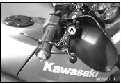
Squeeze the brake lever slowly and hold it with a band [A].
Set the jack under the engine and raise the rear wheel.
Special Tool - Jack: 57001-1238
Remove the seat (see Seat Removal in the Frame chapter).
Remove the Side Covers (see Side Cover Removal in the Frame chapter).
Remove the upper tie-rod bolt [A] and nut.
Remove the mounting bolts [B] and pull off the rear shock absorber [C].
|
13-14 SUSPENSION
Rear Shock Absorber
Remove the upper tie-rod bolt [A] and nut.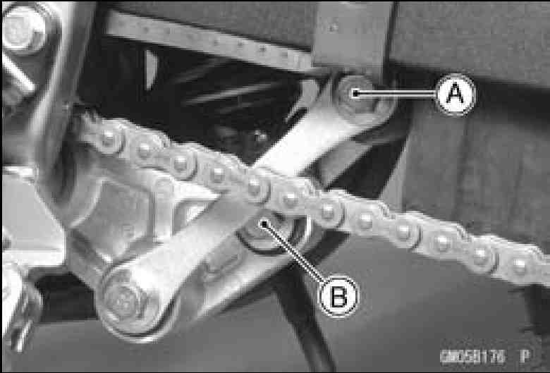
Remove the mounting bolts [B] and pull off the rear shock absorber [C].
• Tighten the mounting bolts.
Torque-Rear Shock Absorber Upper Mounting Nut: 59 N-m (6.0 kgf-m, 43 ft-lb) Rear Shock Absorber Lower Mounting Nut: 98 N-m (10 kgf-m, 72 ft-lb)
• Adjust the rear shock absorber position (see Rear Shock Absorber Adjustment).
Rear Shock Absorber Wear
Remove the rear shock absorbers (see Rear Shock Absorber Removal).
Compress each rear shock absorber.
Visually inspect the following items.
Compression Stroke Oil Leakage Other Damage
• If there is any damage to the rear shock absorber, replace the shock absorbers.
Bushing Wear
Visually inspect the rubber bushing [A].
If it shows any signs of damage, replace it.
Rear Shock Absorber Oil Leak Inspection • Refer to the Rear Shock Absorber Oil Leak Inspection in the Periodic Maintenance chapter.
SUSPENSION 13-15
Swingarm
CAUTION
Do not tap the swingarm pivot shaft when removing or installing. Push or pull the pivot shaft while turning the shaft. Tapping on the shaft could damage the needle bearings in the swingarm.

• Remove:
Rear Wheel (see Rear Wheel Removal in the
Wheels/Tires chapter)
Upper Tie Rod Bolt and Nut
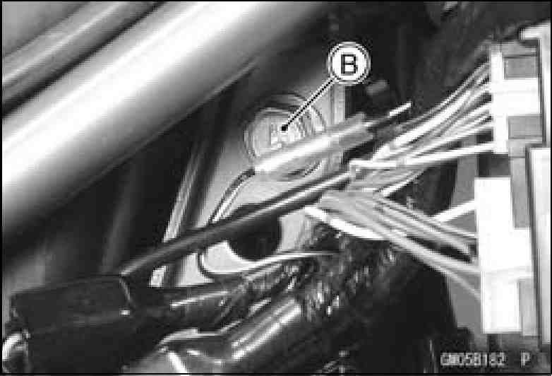
Rear Brake Hose Clamps [A]
Rear Shock Absorber Lower Mounting Bolts and Nut
Chain Cover [B] and Chain Guide
Pivot Shaft Caps
• Remove the pivot shaft nut [A], and pull out the pivot shaft from right side.
NOTE
○Make sure the swingarm dose not catch the Rear Brake Switch.
Swingarm Sleeve and Needle Bearing Wear