

Caution
Immediately wipe up any brake fluid that spills.
WARNING
Do not attempt to drive the motorcycle until a full brake lever is obtained by pumping the brake lever until the pads are against the disc. The brake will not function on the first application of the lever if this is not done.
Brake Hose Installation Note
Replace the both washers with new one.
Install the brake hose with a specified torque.
Torque - Brake Hose Banjo Bolts: 34 N·m (3.5 kgf·m, 25 ft·lb)
Suspension 13-1 13
Подвеска
Table of Contents
Special Tools and Sealant
Front Fork
Front Fork Removal
Front Fork Installation
Front Fork Disassembly
Front Fork Assembly
Inner Tube, Outer Tube Inspection
Dust Seal Inspection
Spring Tension
Rear Shock Absorber
Spring Preload Adjustment
Rear Shock Absorber Removal Rear Shock Absorber Installation Rear Shock Absorber Wear
Rear Shock Absorber Oil Leak Inspection
Swingarm
Swingarm Removal
Swingarm Sleeve and Needle Bearing Wear
Swingarm Installation
Swingarm Disassembly/Assembly
Swingarm Needle Bearing Lubrication
Tie-Rod, Rocker Arm
Tie-Rod Removal
Tie-Rod Installation
Rocker Arm Removal
Rocker Arm Installation
Rocker Arm Bearing, Sleeve Inspection Roc n
13-2 13-6 13-7 13-8 13-8 13-9 13-9 13-10 13-11 13-12 13-12 13-12 13-13 13-13 13-13 13-14 13-14 13-14 13-14 13-15 13-15 13-15 13-16 13-16 13-16 13-16 13-17 13-17 13-17 13-17 13-18 13-18 13-18
13-2 SUSPENSION
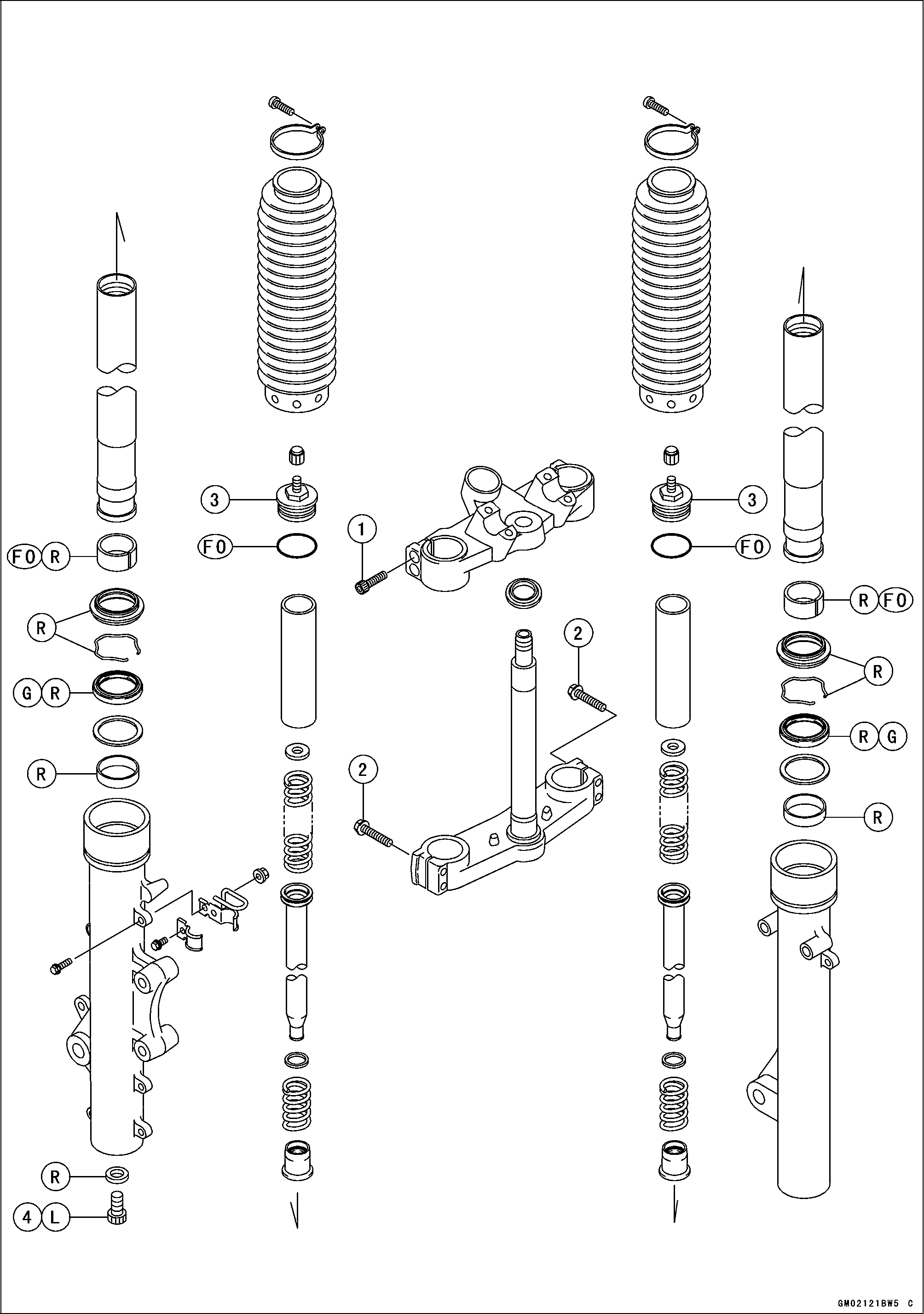
Exploded View
SUSPENSION 13-3
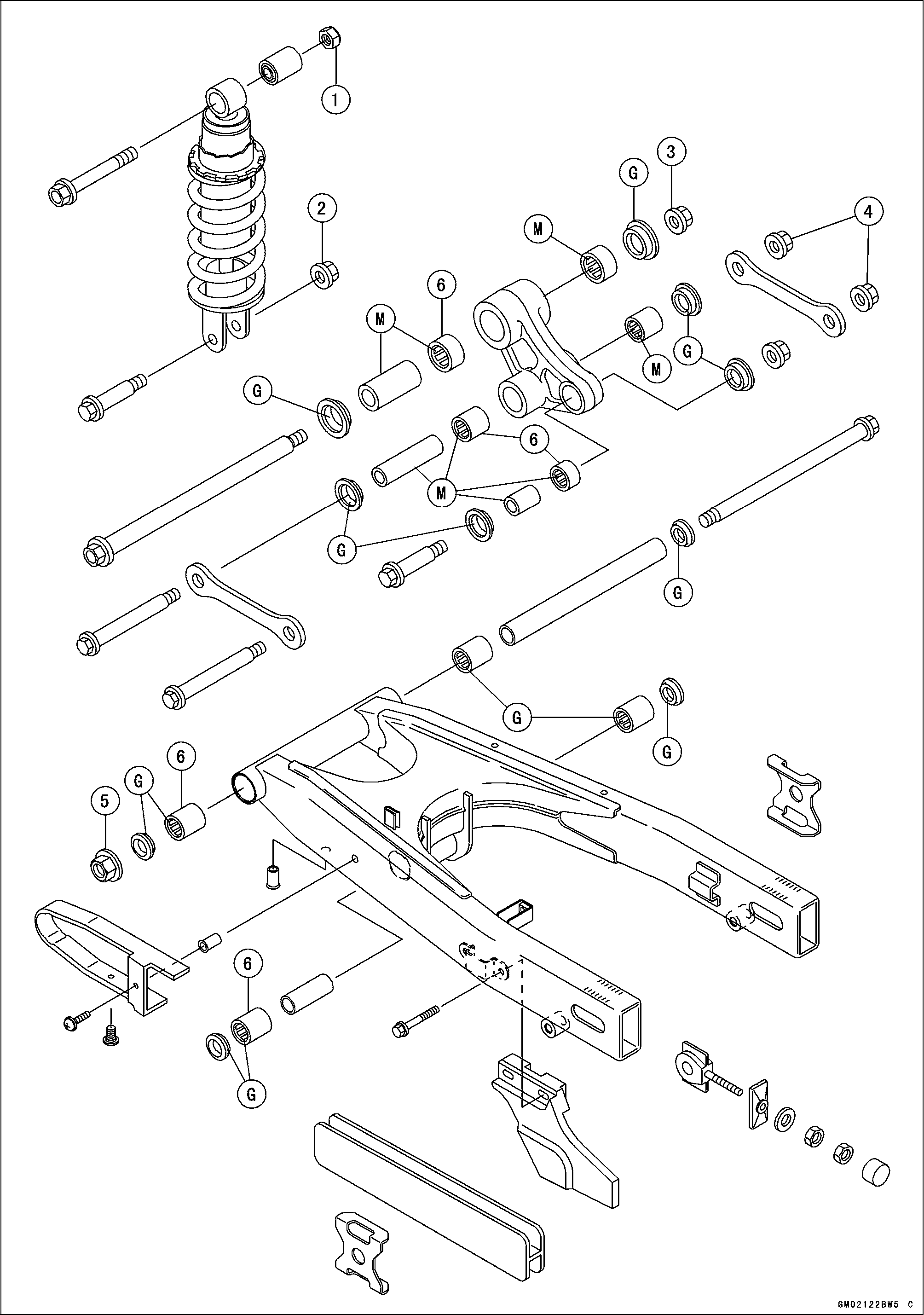
Exploded View
No. |
Fastener |
Torque |
Remarks |
||
N-m |
kgf-m |
ft-lb |
|||
1 |
Front Fork Upper Clamp Bolts |
25 |
2.5 |
18 |
S |
2 |
Front Fork Lower Clamp Bolts |
23 |
2.3 |
16.5 |
|
3 |
Front Fork Top Bolts |
30 |
3.1 |
22 |
|
4 |
Front Fork Bottom Allen Bolts |
30 |
3.1 |
22 |
L |
FO: Apply front oil.
G: Apply grease.
L: Apply a non-permanent locking agent.
R: Replacement Parts
S: Follow the specific tightening sequence. SS: Apply Silicone Sealant.
13-4 SUSPENSION
Exploded View
SUSPENSION 13-5
Exploded View
No. |
Fastener |
Torque |
Remarks |
||
N-m |
kgf-m |
ft-lb |
|||
1 |
Rear Shock Absorber Upper Mounting Nut |
59 |
6.0 |
43 |
|
2 |
Rear Shock Absorber Lower Mounting Nut |
98 |
10 |
72 |
|
3 |
Rocker Arm Pivot Nut |
98 |
10 |
72 |
|
4 |
Tie-rod Mounting Nuts |
98 |
10 |
72 |
|
5 |
Swingarm Pivot Nut |
118 |
12 |
87 |
|
6. Needle Bearings: Face the mark side of it to outside.
G: Apply grease.
M: Apply molybdenum dislfide grease.
13-6 SUSPENSION
Specifications
Item |
Standard |
Service Limit |
Front Fork (per one unit) Fork Inner Tube Diameter Fork Spring Setting Air Pressure Rebound Damper Setting Compression Damper Setting Fork Oil Viscosity Fork Oil Capacity: Completely Dry When Changing Oil Fork Oil Level Fork Spring Free Length |
041 mm (1.61 in.) Non-adjustable 0 kPa (Adjustable) Non-adjustable Non-adjustable KAYABA KHL34-G10 or equivalent 530 ±4 mL (17.91 ±0.14 US oz.) approx. 453 mL (5.31 US oz.) Fully compressed, without fork spring, below from inner tube top 194 ±2 mm (7.64 ±0.08 in.) 522.5 mm (20.57 in.) |
––– ––– ––– ––– ––– ––– ––– ––– ––– 512 mm (20.16 in.) |
Rear Shock Absorber Rebound Damper Set Compression Damper Set Spring Setting Position Gas Pressure |
Non-adjustable Non-adjustable No. 2 of 5 positions 980 kPa (10 kgf/cm²) |
|
SUSPENSION 13-7
Special Tools and Sealant
Fork Outer Tube Weight: 57001-1218
|
|
|
|
|
|
|
|
1 |
|
р |
|
|
ST571218ST С |
^Ю_ |
|
|

Front Fork Oil Seal Driver: 57001-1219

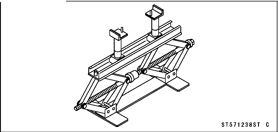
Jack: 57001-1238
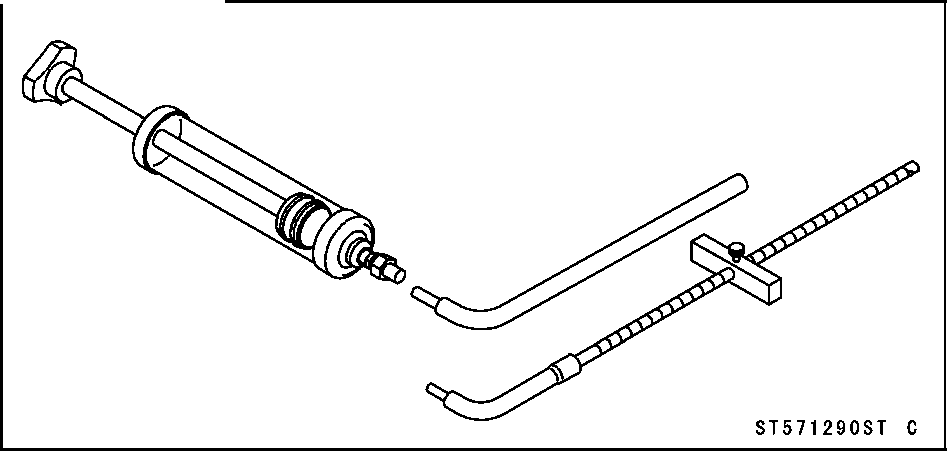
Fork Oil Level Gauge: 57001-1290
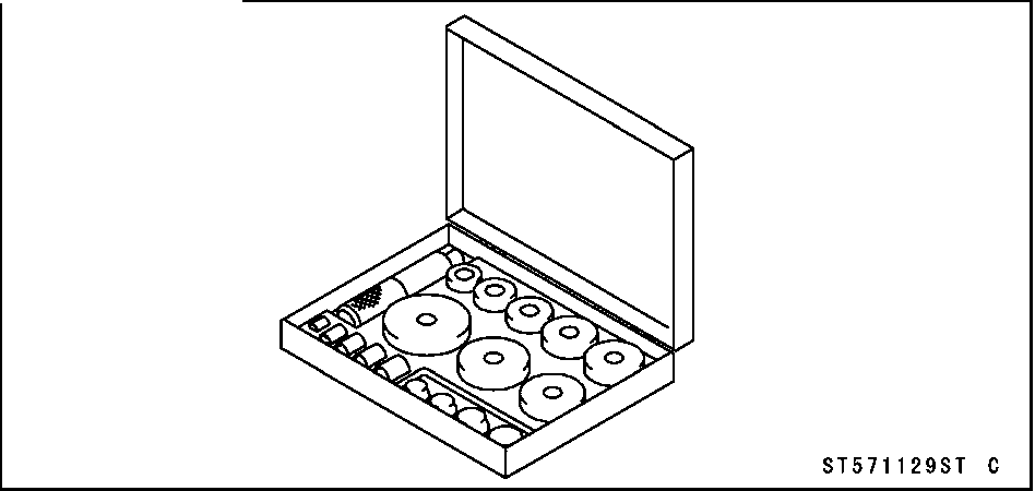
Bearing Driver Set: 57001-1129
13-8 SUSPENSION
Front Fork
Remove the front fork (see Front Fork Removal).
Remove the fork boot from the front fork.
Hold the outer tube vertically in a vise.
Remove:
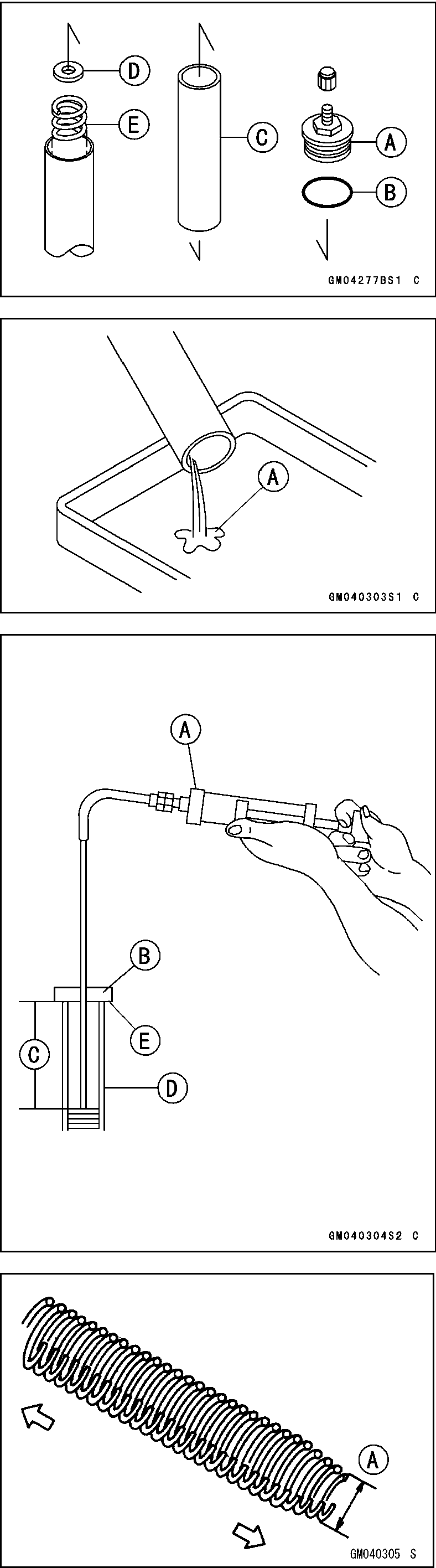
Top Bolt [A] and O-ring [B] Spacer [C] Fork Spring Seat [D] Fork Spring [E]
Pour out the fork oil [A] with the fork upside down.
Fill the front fork with the specified oil.
Fork Oil Viscosity: KAYABA KHL34-G10 or equivalent
Fork Oil Capacity (when changing oil):
Approx. 453 mL (15.31 US oz.)
Wait for about five minutes so that any suspended air bubbles can surface.
Measure the oil level, using the fork oil level gauge [A].
Special Tool - Fork Oil Level Gauge: 57001-1290
OSet the gauge stopper [B] so that its lower side shows the
oil level distance specified [C]. OInsert the gauge tube into the inner tube [D] and position
the stopper across the top of the inner tube [E]. OPull the handle slowly to draw out the excess oil until no
more oil comes up the tube.
• If no oil is drawn out, there is not enough oil in the fork. Pour in some more oil, then draw out the excess.
Front Fork Oil Level (Fully compressed without fork spring) Standard: 194 ±2 mm (7.64 ±0.08 in.)
Install the fork spring with the smaller diameter end [A] facing down.
Install:
Fork Spring Seat Spacer
• Install the top bolt with a specified torque.
Torque - Front Fork Top Bolt: 30 N-m (3.1 kgf-m, 22 ft-lb)
Install the fork boot to the front fork.
Install the front fork (see Front Fork Installation). Repeat the same procedure for another front fork.
SUSPENSION 13-9 Front Fork
• Remove:
Brake Hose Clamps (Left Front Fork only)
Front Wheel (see Front Wheel Removal in the
Wheels/Tires chapter)
Front Fender (see Front Fender Removal in the Frame
chapter)
Front Brake Caliper Mounting Bolts
Front Brake Hose Clamp Mounting Bolt
Speedometer Cable Clamp Mounting Bolt
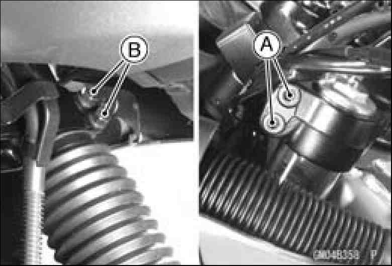
Loosen the upper [A] and lower [B] fork clamp bolts.
It is necessary to loosen the front fork top bolt, if the front fork shall be disassembled. With a twisting motion, work the fork leg down and out.
• Install the fork tube so that the top of the fork inner tube [A] is aligned with the upper surface of the steering stem head [B].
NOTE
OTighten the two clamp bolts alternately two times to ensure even tightening torque.
Run the cables, wires, and hoses as shown in the Cable, Wire and Hose Routing in the Appendix chapter.
Install the front wheel (see Front Wheel Installation in the Wheels/Tires chapter).
Torque - Upper Fork Clamp Bolts: 25 N·m (2.5 kgf·m, 18
ft·lb) Lower Fork Clamp Bolts: 23 N·m (2.3 kgf·m, 16.5
ft·lb) Brake Caliper Mounting Bolts: 34 N·m (3.5 kgf·m,
25 ft·lb)
Check the front brake effectiveness after installation.
![]()
Do not attempt to ride the motorcycle until a full brake lever is obtained by pumping the brake lever until the pads are against the disc. The brake will not function on the first application of the lever if this is not done.
Install the fork boot to the front fork.
13-10 SUSPENSION
Front Fork
• Remove the front fork (see Front Fork Removal).
•○DThraeinfotlhloewfionrgk poailr(tsseaereFrroenmt oFvoerdk dOuilriCnghadnrgaein)i.ng the fork
oil.
Top Bolt and O-ring Spacer
Fork Spring Seat Fork Spring
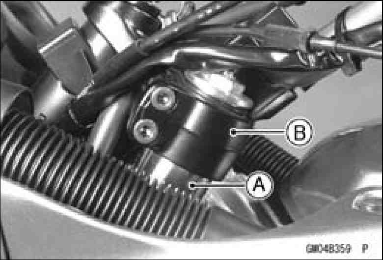
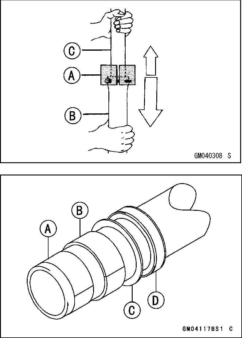
Hold the front fork horizontally in a vise [A].
Stop the cylinder unit [B] from turning by using the special tools.
Unscrew the Allen bolt [C], and take the gasket out of the bottom of the outer tube.
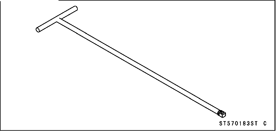
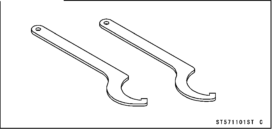
Special Tools - Fork Cylinder Holder Handle: 57001-183 [D] Fork Cylinder Holder Adapter: 57001-1057 [E]
• Take the cylinder unit out of the inner tube.
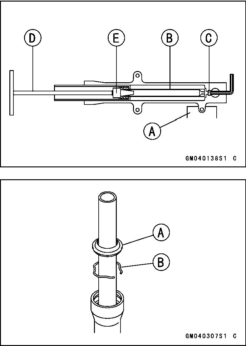
•○SReepmaoraveteththeedinunstesr etuabl e[Af]rofrmomthteheouotuetretrutbuebsea. s follows: ○Remove the retaining ring [B] from the outer tube.
Special Tool - Fork Outer Tube Weight: 57001-1218
○Take out the cylinder base out of the outer tube.
• Remove the guide bushings [A], outer tube guide bushing [B], washer [C], and oil seal [D] from the inner tube.
SUSPENSION 13-11
Front Fork
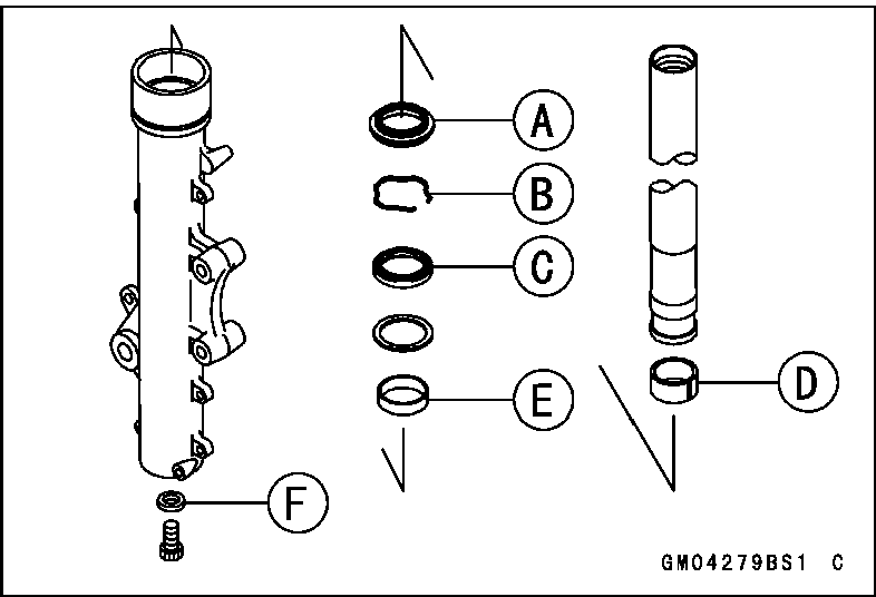
• Replace the following parts with new ones after removal.
Dust Seal [A]
Retaining Ring [B]
Oil Seal [C]
Inner Guide Bushing [D]
Outer Guide Bushing [E]
Bottom Allen Bolt Gasket [F]
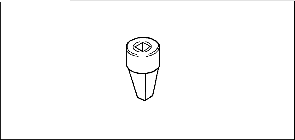
• Put the cylinder unit [A] with the spring into the inner tube [B] protruding from the inner tube, and install the cylinder base [C] onto the bottom end of the cylinder unit.
○Install the cylinder base with the tapered end [D] up.
• Install the inner tube, cylinder unit, and cylinder base as a set into the outer tube.
|
|
|
|
|
pn \ |
|
|
|
|
®- |
\ |
|
|
-® |
|
О |
|
||
|
|
|||
|
|
|||
GM040311S1 С |
||||
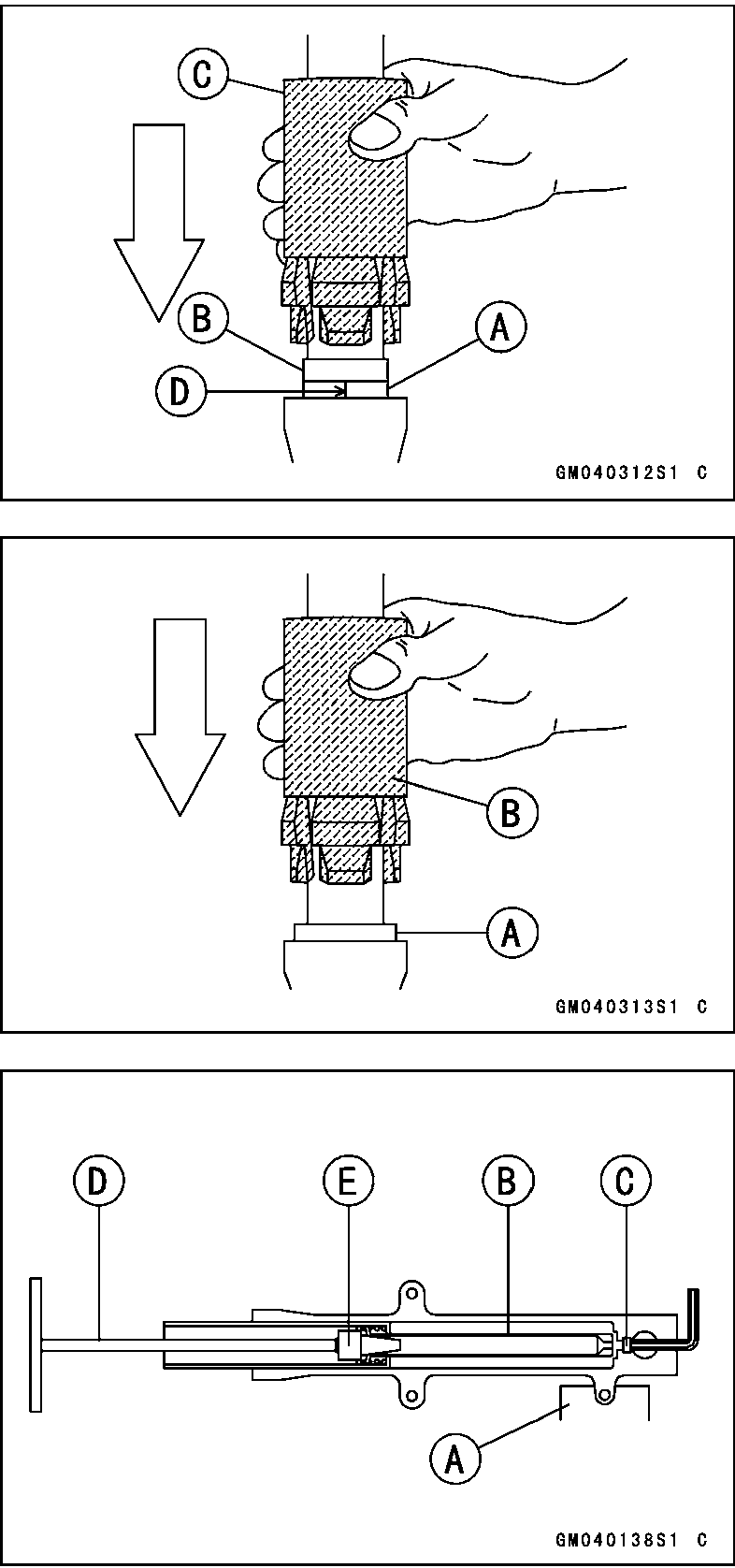
○The split [D] of the bushing should face toward the side of the vehicle.
Special Tool - Front Fork Oil Seal Driver: 57001-1219
• Apply grease to the oil seal lips and install the washer and the oil seal [A] into the outer tube.
Special Tool - Front Fork Oil Seal Driver: 57001-1219 [B]
• Install:
Retaining Ring Dust Seal
Hold the front fork horizontally in a vise [A].
Apply a non-permanent locking agent to the threads of the Allen bolt and screw the Allen bolt into the bottom of the outer tube.
Hold the cylinder unit [B] with the special tools and tighten the Allen bolt [C].
Special Tools-Fork Cylinder Holder Handle: 57001-183 [D] Fork Cylinder Holder Adapter: 57001-1057 [E]
Torque - Bottom Allen Bolt: 30 N-m (3.1 kgf-m, 22 ft-lb)
13-12 SUSPENSION
Front Fork
Fork Oil Viscosity: KAYABA KHL34-G10 or equivalent Fork Oil Capacity (completely dry):
530 ±4 mL (17.91 ±0.14 US oz.)
Inner Tube, Outer Tube Inspection
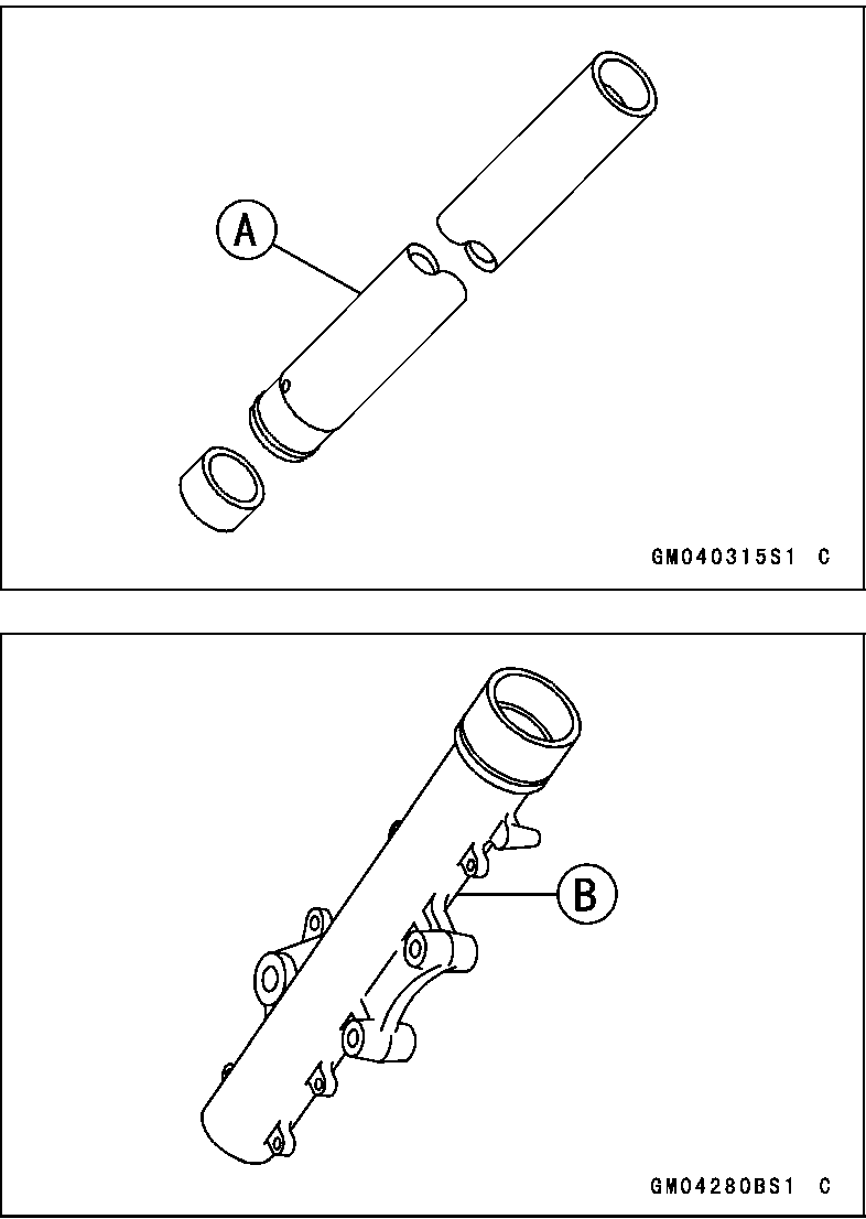
Visually inspect the inner tube [A] for scoring or scratches on the outer surface of it and repair any damage.
Nick or rust damage can sometimes be repaired by using a wet- stone to remove sharp edges or raised areas which cause seal damage.
If the damage is not repairable, replace the inner tube. Since damage to the inner tube damages the oil seal, replace the oil seal whenever the inner tube is repaired or replaced.