
- •Idle Speed Adjustment
- •Отметить
- •Предостережение
- •Предостережение
- •Отметить
- •Отметить
- •If any spoke brakes, it should be replaced immediately. A missing spoke places an additional load on the other spokes, which will eventually cause other spokes to break.
- •Caution
- •Caution
- •If dirt or dust is allowed to pass through into the throttle assy, the throttle may become stuck, possibly causing an accident. Caution
- •If dirt gets through into the engine, excessive engine wear and possibly engine damage will occur.
- •Caution
- •Caution
- •3.0 L (When filter is removed)
- •3.4 L (When engine is completely dry)
- •A warning
- •Install the clamp screws horizontally as shown. Otherwise the screws could come in contact with the vacuum adjusting screws, resulting in an unsafe riding condition.
- •Caution
- •Caution
- •Caution
- •Caution
- •If dirt or dust is allowed to pass through into the carburetor, the throttle may become stuck, possibly causing accident. Caution
- •If dirt gets through into the engine, excessive engine wear and possibly engine damage will occur.
- •Caution
- •Coolant Flow Chart
- •Caution
- •Caution
- •Valve Closing Temperature (for reference)
- •Caution
- •Caution
- •Caution
- •Caution
- •Caution
- •Caution
- •Caution
- •Inlet sprocket must use "l" marked bolt holes. Exhaust sprocket must use "e" marked bolt holes.
- •Valve Seating Surface Outside Diameter
- •Valve Seating Surface Width
- •Valve/Valve Guide Clearance (Wobble Method)
- •Valve Seat Cutter Holder - 05.5 Valve Seat Cutter Holders Bar
- •Caution
- •5700-1097 [C] Piston Base, 02.3: 5700-1336 [d]
- •Install the clamp screws horizontally. Otherwise the screws could come in contact with the vacuum adjusting screws, resulting in an unsafe riding condition.
- •Caution
- •Caution
- •Caution
- •If new dry steel plates and friction plates are installed, apply engine oil to the surfaces of each plate to avoid clutch plate seizure.
- •Caution
- •Caution
- •If the oil passage plug is removed while the engine is warm, hot engine oil will drain through the oil passage; take care against burns.
- •Оглавление
- •Caution
- •Коленчатый вал/Коробка Передач
- •92028-1692 Crankcase
- •Caution
- •Caution
- •Caution
- •Caution
- •Caution
- •Inside Circlip Pliers: 57001-143
- •Caution
- •A warning
- •Caution
- •Caution
- •Caution
- •Final drive 11-1 11
- •Inside Circlip Pliers: 57001-143
- •Brakes 12-1 12
- •Inside Circlip Pliers: 57001-143
- •Immediately wash away any brake fluid that spills.
- •Caution
- •Immediately wash away any brake fluid that spills.
- •Immediately wipe up any brake fluid that spills.
- •Caution
- •Immediately wipe up any brake fluid that spills.
- •Suspension 13-1 13
- •Caution
- •If the inner tune is badly bent or creased, replace it. Excessive bending, followed by subsequent straightening, can weaken the inner tube.
- •Caution
- •Caution
- •Steering 14-1 14
- •Table of Contents
- •A warning
- •Frame 15-1 15
- •Inspection.................................. 16-46
- •Installation ................................. 16-51
- •Inspection.................................. 16-61
- •Inspection.................................. 16-62
- •Igniter Checker Assembly: 57001-1378
- •Caution
- •Initial Charge
- •Caution
- •Caution
- •If by chance an excessive amount of gas is generated due to overcharging, the safety valve operates to keep the battery safe.
- •Caution
- •If possible, do not quick charge. If the quick charge is done due to unavoidable circumstances, do standard charge later on.
- •Caution
- •Caution
- •Caution
- •Caution
- •Ignition System
- •Ignition System Circuit
- •Ignition System
- •Caution
- •Ignition System
- •Ignition System
- •Ignition Timing
- •Ignition System
- •Caution
- •Ic Igniter Operation Voltage Check
- •Ignition System
- •Ic Igniter Operation Voltage: Battery Voltage
- •Ignition Coil Primary Peak Voltage Inspection
- •Ignition System
- •Ignition Coil Primary Peak Voltage Standard: dc100 V or more
- •Ignition System
- •Ignition System
- •Ignition System note
- •Caution
- •Valve noise:
Caution
|
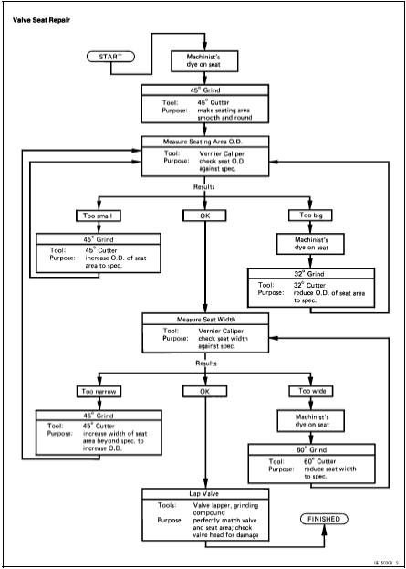
The 32° cutter removes material very quickly. Check the seat outside diameter frequently to prevent overgrinding.
To measure the seat width, use a vernier caliper to measure the width of the 45° angle portion of the seat at several places around the seat.
If the seat width is too narrow, repeat the 45° grind until the seat is slightly too wide, and then return to the seat O.D. measurement step above.
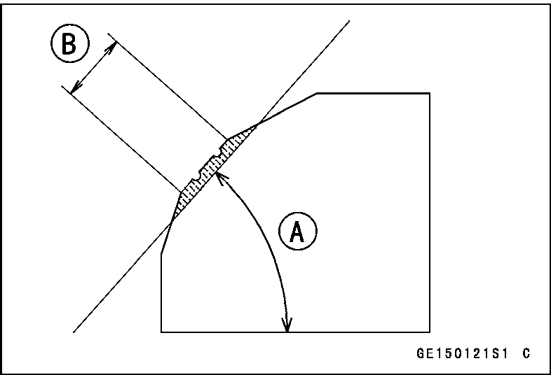
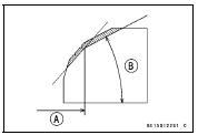
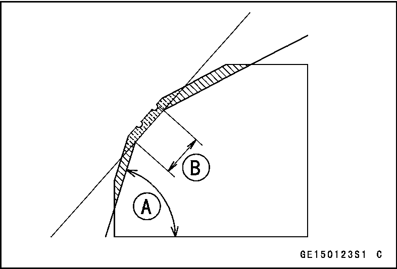
If the seat width is too wide, make the 60° [A] grind described below.
If the seat width is within the specified range, lap the valve to the seat as described below.
Grind the seat at a 60° angle until the seat width is within the specified range.
OTo make the 60° grind, fit a 60° cutter to the holder, and slide it into the valve guide.
OTurn the holder, while pressing down lightly.
OAfter making the 60° grind, return to the seat width measurement step above. Correct Width [B]
5-30 ENGINE TOP END
Valves
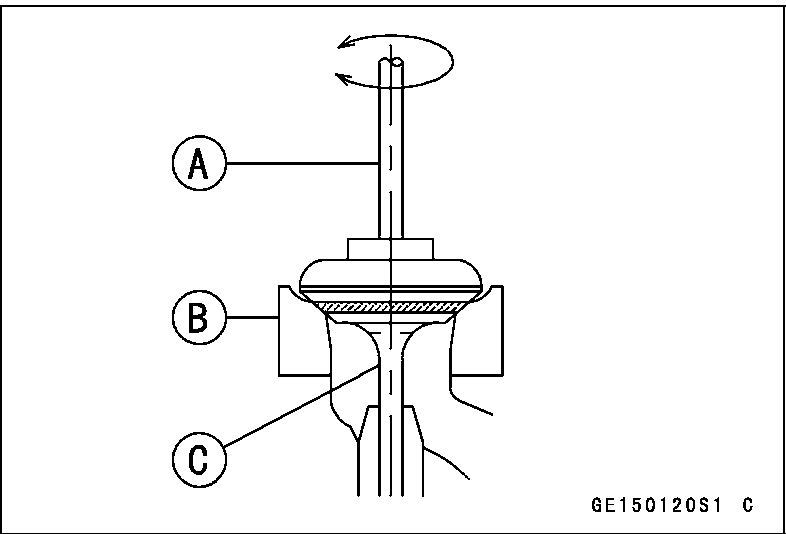
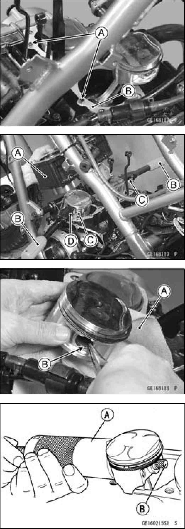
OPut a little coarse grinding compound on the face of the valve in a number of places around the valve head.
OSpin the valve against the seat until the grinding compound produces a smooth, matched surface on both the seat and the valve.
ORepeat the process with a fine grinding compound.
Lapper
Valve Seat
Valve
The seating area should be marked about in the middle of the valve face.
If the seat area is not in the right place on the valve, check to be sure the valve is the correct part. If it is, it may have been refaced too much; replace it.
Be sure to remove all grinding compound before assembly.
When the engine is assembled, be sure to adjust the valve clearance (see Valve Clearance Adjustment in the Periodic Maintenance chapter).
ENGINE TOP END 5-31
Valves
|
5-32 ENGINE TOP END
Cylinder, Piston
Cylinder Removal
Remove
the
cylinder
head
(see
Cylinder
Head
Removal).
Remove
the
main
oil
pipe
mounting
bolt.
Remove
the
bolts
[A]
and
pull
out
the
water
pipe
with
water
pump cover [B] (see water pump removal in the Cooling
System chapter).
Take
out
the
cylinder
block
so
as
not
to
damage
the
main
oil
pipe.
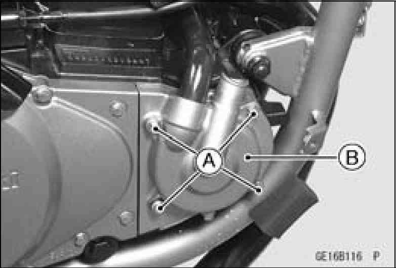
Cylinder Installation
• Install:
Dowel Pins [A]
New Cylinder Base Gasket [B] OInstall the cylinder base gasket so that the swallen groove come to upper side.
Apply molybdenum disulfide oil to the cylinder bore.
Position the crankshaft so that all the piston heads are almost level.
Install the cylinder block [A].
Special Tool - Piston Ring Compressor Grip: 5700-1095
[B] Piston Ring Compressor Belt, 067 ~ 079: