

Caution
Do not apply compressed air to the air vent holes [B] in the tank cap. This could cause damage and clogging of the labyrinth in the cap.
3-24 FUEL SYSTEM
Fuel Hose
Fuel Hose and Connection Inspection • Refer to the Fuel Hoses and Connections Inspection in the Periodic Maintenance chapter.
COOLING SYSTEM 4-1
Система охлаждения
Table of Contents
Технические требования
Специальный Инструмент и Изолятор
Карта Регулирования циркуляции охлаждающей жидкости
Хладагент
Осмотр Ухудшения хладагента
Осмотр Уровня охлаждающей жидкости
Дренаж хладагента
Заполнение хладагента
Визуальный Осмотр Утечки
Испытание Давления Системы охлаждения
Смывание
Очистка Фильтра хладагента
Осмотр Клапана хладагента
Водяной насос
Удаление Водяного насоса
Установка Водяного насоса
Механический Осмотр Изоляции
Разборка Кожуха Водяного насоса
Сборка Кожухов Водяного насоса
Сборка рабочих колес
Осмотр Рабочего колеса насоса
Радиатор, Вентилятор Радиатора
Удаление радиатора
Осмотр радиатора
Удаление Вентилятора радиатора
Осмотр Шеи наполнителя
Осмотр Крышки радиатора
Шланг радиатора и Осмотр Связи
Шланг радиатора, Шланг Воздуховода, Установка Шланга Резервуара
Термостат
Удаление термостата
Установка термостата
Осмотр термостата
Выключатель Вентилятора радиатора, Водный Температурный Выключатель
Удаление Выключателя Вентилятора радиатора
Выключатель Вентилятора радиатора, Водная Температура
Выключатель Вентилятора радиатора, Водная Температура Переключает Осмотр
Воденая температура переклячает удаление
4-2
4-4
4-5
4-6
4-8
4-8
4-8
4-8
4-8
4-8
4-8
4-9
4-9
4-9
4-10
4-10
4-10
4-11
4-11
4-11
4-12
4-12
4-13
4-13
4-13
4-14
4-14
4-14
4-15
4-15
4-16
4-16
4-16
4-16
4-18
4-18
4-18
4-18
4-18
4
4-2 COOLING SYSTEM
Exploded View
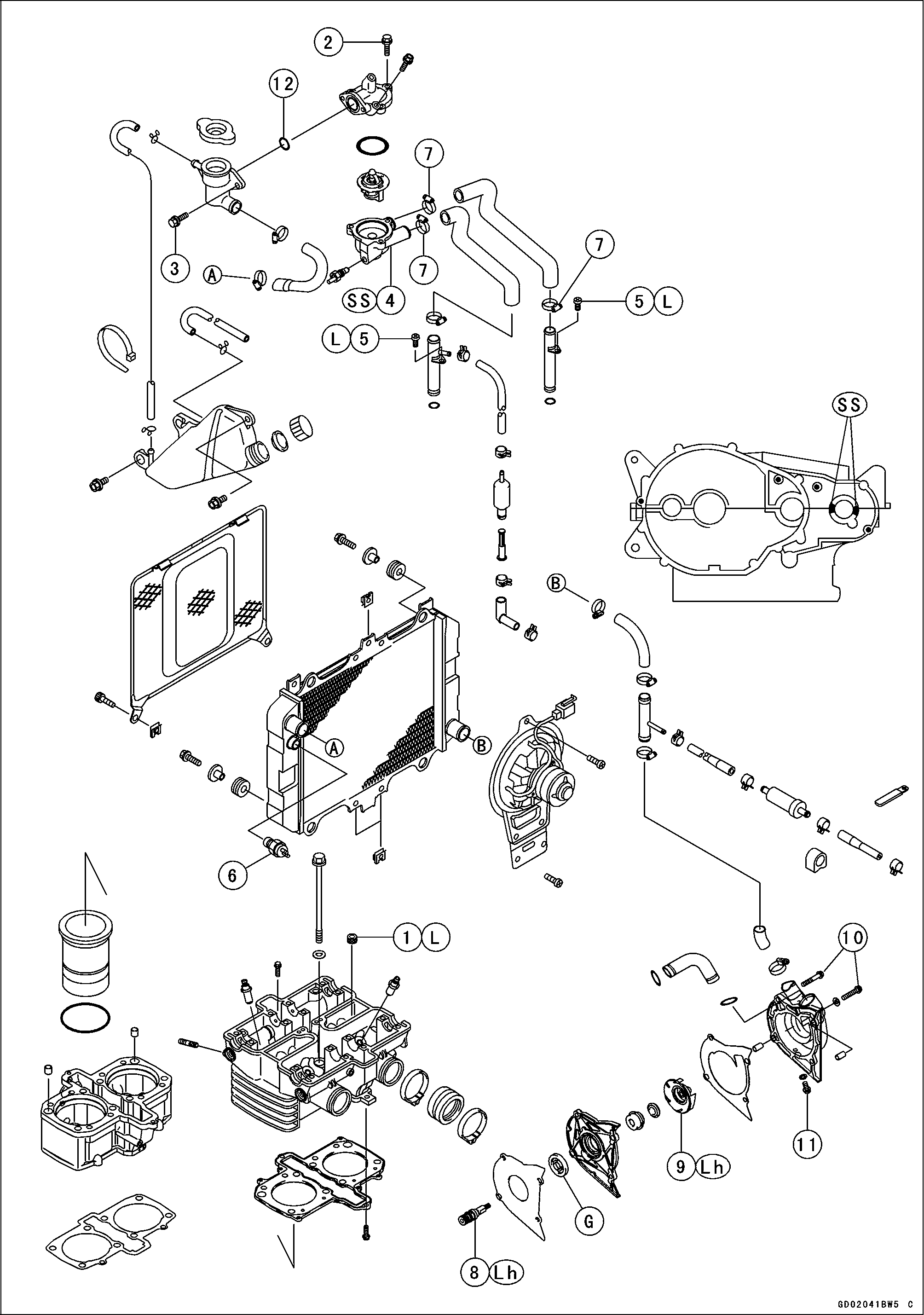
COOLING SYSTEM 4-3
Exploded View
No. |
Fastener |
Torque |
Remarks |
||
N-m |
kgf-m |
ft-lb |
|||
1 |
Cylinder Head Jacket Plug |
9.8 |
1.0 |
87 in·lb |
L |
2 |
Thermostat Housing Bolts |
11 |
1.1 |
95 in·lb |
|
3 |
Radiator Cap Holder Mounting Bolts |
11 |
1.1 |
95 in·lb |
|
4 |
Water Temperature Switch |
7.8 |
0.8 |
69 in·lb |
SS |
5 |
Water Pipe Bolts |
9.8 |
1.0 |
87 in·lb |
L |
6 |
Radiator Fan Switch |
18 |
1.8 |
13 |
|
7 |
Radiator Hose Clamp Screws |
2.5 |
0.25 |
22 in·lb |
|
8 |
Water Pump Shaft |
25 |
2.5 |
18 |
Lh |
9 |
Water Pump Impeller |
9.8 |
1.0 |
87 in·lb |
Lh |
10 |
Water Pump Cover Bolts |
11 |
1.1 |
95 in·lb |
|
11 |
Coolant Drain Bolt |
11 |
1.1 |
95 in·lb |
|
12. Thermostat
G: Apply high temperature grease.
L: Apply a non-permanent locking agent. Lh: Left-hand Thread SS: Apply silicone sealant.
4-4 COOLING SYSTEM
Specifications
Item |
Standard |
Coolant Provided when Shipping Type (recommended) Color Mixed Ratio Freezing Point Total Amount |
Permanent type antifreeze (soft water and ethylene glycol plus corrosion and rust inhibitor chemicals for aluminum engines and radiators) Green Soft water 50%, coolant 50% –35°C (–31°F) 1.7 L (1.8 US qt) (reserve tank full level including radiator and engine) |
Radiator Cap Relief Pressure |
93-123 кРа (0.95 ~ 1.25 kgf/cm2, 14-18 psi) |
Thermostat Valve Opening Temperature Valve Full Opening Lift |
80.5 - 83.5°С (177 - 182°F) 8 mm (0.31 in.) or more @95°C (203°F) |
COOLING SYSTEM 4-5
Special Tool and Sealant

Kawasaki Bond (Silicone Sealant): 56019-120
4-6 COOLING SYSTEM
Coolant Flow Chart
Permanent type antifreeze is used as a coolant to protect the cooling system from rust and corrosion. When the engine starts, the water pump turns and the coolant circulates.
The thermostat is a wax pellet type which opens or closes with coolant temperature changes. The thermostat continuously changes its valve opening to keep the coolant temperature at the proper level. When coolant temperature is below 80.5 ∼ 83.5°C (177 ∼ 182°F), the thermostat closes so that the coolant flow is restricted through the air bleeder hole, causing the engine to warm up more quickly. When coolant temperature is more than 80.5 ∼ 83.5°C, the thermostat opens and the coolant flows.
When the coolant temperature goes up beyond 96 ∼ 100°C (205 ∼ 212°F), the radiator fan switch conducts to operate the radiator fan. The radiator fan draws air through the radiator core when there is not sufficient air flow such as at low speeds. This increases up the cooling action of the radiator. When the temperature is below 91°C (196°F) temperature less than ON temperature, the fan switch opens and the radiator fan stops.
In this way, this system controls the engine temperature within narrow limits where the engine operates most efficiently even if the engine load varies.
The system is pressurized by the radiator cap to suppress boiling and the resultant air bubbles which can cause engine overheating. As the engine warms up, the coolant in the radiator and the water jacket expands. The excess coolant flows through the radiator cap and hose to the reserve tank to be stored there temporarily. Conversely, as the engine cools down, the coolant in the radiator and the water jacket contracts, and the stored coolant flows back to the radiator from the reserve tank.
The radiator cap has two valves. One is a pressure valve which holds the pressure in the system when the engine is running. When the pressure exceeds 93 ∼ 123 kPa (0.95 ∼ 1.25 kgf/cm², 14 ∼ 18 psi), the pressure valve opens and releases the pressure to the reserve tank. As soon as pressure escapes, the valve closes, and keeps the pressure at 93 ∼ 123 kPa (0.95 ∼ 1.25 kgf/cm², 14 ∼ 18 psi). When the engine cools down, another small valve (vacuum valve) in the cap opens. As the coolant cools, the coolant contracts to form a vacuum in the system. The vacuum valve opens and allows the coolant from the reserve tank to enter the radiator.