Fig. 10.4. Scheme of the rotor dynamic balancing
The cross-sectional movements of the balancing machine elastic support will be missing, when a centrifugal inertia force of the rotor unbalanced weights, concentrated in the zone of this support
Рj un = mr e 2
Will be compensated by centrifugal force of balanced elements weights
Рj b = mb r 2.
Therefore, the requirement of a full dynamic balancing will be written this way:
Рj un = Рj b or mr e = mb r. (10.8)
The requirement (10.8) can’t be met completely. The residual dynamic unbalance has the same values as static unbalance:
residual = 5…50 gsm = (5…50)10-5 kgm.
10.3.3. The procedures of the vibration level lowering at maintenance stage
At stage of GTE maintenance the main way to prevent inadmissible increase of vibration level is the vibrational control and vibration parameters change forecasting (vibrational monitoring of the engine). In the process of such control the dynamics of the recorded vibration levels changes is analyzed and value of engine operating time before possible dangerous vibrational condition is forecasted with the help of mathematical methods. The vibrational monitoring of modern turbine engines is executed with onboard and ground computer being used.
Questions for self-check
1. What are the sources of gas turbine engine vibrations?
2. Explain how can the gas turbine engine vibration level be controlled by vibration overload factor.
3. Explain how can the gas turbine engine vibration level be controlled by amplitude of vibration velocity.
4. Compare gas turbine engine vibration level control by vibration overload factor and amplitude of vibration velocity.
5. What procedures to lower vibration level are applied at stage of designing?
6. What is gas turbine engine static balancing?
7. What is gas turbine engine dynamic balancing?
8. How can an inadmissible increase in vibration levels of gas turbine engine be prevented at the stage of their maintenance?
Сhapter 11. Gas turbine engine rotor supports
11.1. Brief data about gas turbine engine rotor supports.
11.2. Calculation of support bearings.
Literature: [1], p.173–193; [3], p.453–480; [4], p.267–276; [6], p.462–473; [15].
11.1. Brief data about gas turbine engine rotor supports
The supports serve for rotor fixation in a load-bearing casing of the engine. The capability of the rotor rotation with a given speed and least friction should be provided. For this purpose there are rolling bearings (ball and roller) in the supports.
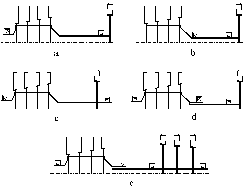
Fig. 11.1. Typical schemes of bearing allocation in engines with two-support (a, b, c),
three-support (d) and four-support (e) rotors
There are typical schemes of bearing allocation in engines (see Fig. 11.1):
- the two-support rotor with console turbine arrangement (Fig. 11.1, a);
- the two-support rotor with console turbine and compressor arrangement (Fig. 11.1, b);
- the two-support rotor with turbine and compressor arrangement between supports (Fig. 11.1, c);
- the three-support rotor (Fig. 11.1, d);
- the four-support rotor (Fig. 11.1, e).
The ball bearings provide rotor fixation in two directions – radial and axial (see Fig 11.2, a).
The roller bearings provide rotor fixation only in a radial direction (see Fig 11.2, b). They permit axial displacement of rotor about the GTE casing caused by operational loads and temperature.
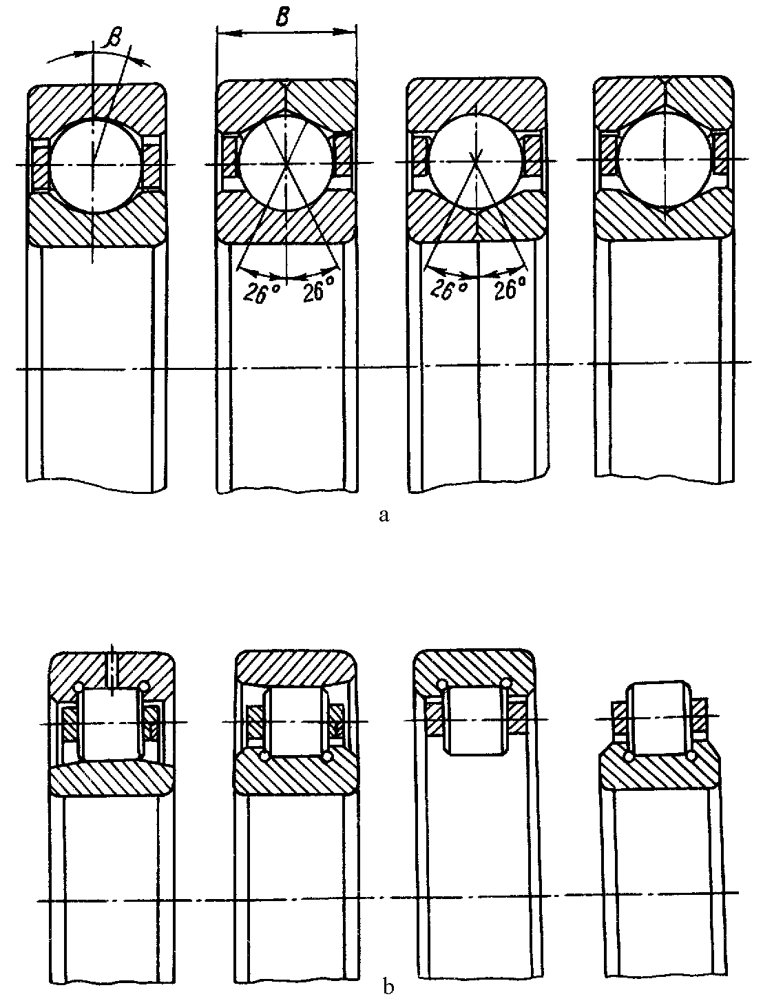
Fig 11.2. Rolling bearings:
a – ball bearings; b – roller bearings
We apply one ball bearing and the rest are roller bearings for one GTE rotor (which consists of compressor and turbine rotors). The GTE rotor support consists of two parts: support casing and bearing unit.
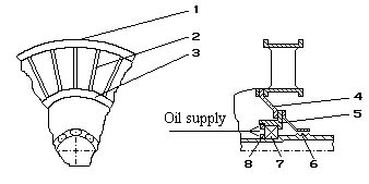
The support casing has five structural elements (Fig. 11.3):
external load-bearing ring 1;
radial load-bearing elements 2;
internal load-bearing ring 3;
load-bearing diaphragm 4;
bearing casing 5.