
- •Foreword
- •Предисловие
- •Chapter 1. Introduction
- •From the history of aeroengines development. Classification of air gas turbine engines
- •Table 1.1
- •Table 1.2
- •1.2. Design features of manifold types of gas turbine engines
- •Main specifications for some serial turboprop and turboshaft
- •Fig. 1.3. Principal scheme of a two-shaft afterburning
- •Fig. 1.4. Principal scheme of a two-shaft tfe
- •Fig. 1.5. Principal scheme of a three-shaft tfe
- •Fig. 1.8. Principal scheme of a tpfe with a coaxial propfan
- •Main stages of gas turbine engines creation
- •1.4. Absolute and specific parameters of gas turbine engines
- •1.4.1. Absolute and specific parameters of turbojet engines
- •1.4.2. Absolute and specific parameters of turboprop engines
- •I.5. Air gas turbine engine’s lives
- •1.5.1. Nomenclature of lives
- •1.5.2. Sequence of assigning, setting and increase of lives
- •1.5.3. General requirements to life testing of engines and their main elements
- •1.5.4. Forming of test cycles
- •1.5.5. Forming of programs of life tests
- •Questions for self-check
- •2.1. Types of loads acting upon gas turbine engine structural elements
- •2.1.1. Classification of loads
- •2.1.2. Gas loads
- •2.1.3. Mass (inertial) forces and momenta
- •2.1.4. Temperature stresses
- •Fig. 2.4. For determination of the centrifugal forces
- •Fig. 2.5. For determination of the disc temperature stresses
- •2.1.5. Concept of dynamic loads
- •Fig. 2.9. Gas flow velocity behind nozzle vanes
- •2.2. Axial gas forces coming into action in gas turbine engines. Formation of thrust in gas turbine engines of manifold types
- •2.2.1. Axial gas forces acting on the basic gas turbine engine units
- •Fig. 2.10. Scheme of axial forces acting on basic gte units
- •2.3. Determination of axial gas force acting on impeller of gas turbine engine centrifugal compressor
- •2.4. Torques coming into action in gas turbine engines. Balance of torques
- •In gas turbine engines
- •2.4.1. Torques in turbine and compressor
- •Fig. 2.14. For determination of turbine rotor wheel torque
- •2.4.2. Torque balance in gas turbine engines of manifold types
- •Questions for self-check
- •Engine blades
- •Loads acting on blades. The blade stressed state characteristic
- •Fig. 3.1. Loads acting on the blade (a) and the scheme of blade loading
- •Determination of rotor blade tensile stress caused by centrifugal forces
- •The design scheme
- •3.2.2. Equation of a rotor blade stressed state
- •Integrating equation (3.3) in view of the ratio (3.1), we will get
- •3.2.3. Calculation of tensile stress at manifold laws of change of blade section area along its length
- •If the blade section area decreases from the root to periphery under the linear law:
- •In this case an integration by formula (3.7) yields
- •Determination of rotor blade bending stress caused by gas forces
- •3.3.1. Design scheme of a blade
- •3.3.2. Determination of gas load intensities
- •Determination of the bending momenta in axial and circumferential planes
- •3.3.4. Determination of the blade section geometrical characteristics
- •Determination of bending stress caused by gas force
- •Determination of rotor blade bending stress caused by centrifugal forces
- •The design scheme
- •3.4.2. Equation of the bending momenta
- •3.5. Guide and nozzle diaphragm vanes strength calculation features
- •3.5.1. Console type vanes
- •3.5.2. Double-support vanes
- •3.5.3. Frame type vanes
- •3.6. Evaluation of gte rotor blades strength
- •3.6.1. Grounding of blade stressed state criterion
- •3.6.2. Estimation of the blade temperature
- •3.6.3. Determination of blade strength safety factor coefficients
- •Questions for self-check
- •4.1. Loads affecting discs
- •The design scheme and assumptions made at disc strength calculations
- •Fig.4.1. Design scheme of the disc
- •4.3. Design ratings
- •4.4. Disc thermal condition
- •4.5. The disc stressed state equation. Boundary conditions
- •4.5.1. An equilibrium equation
- •4.5.2. Equation of deformations generality
- •4.5.3. Determination of stresses in rotating, unevenly heated elastic disc with an arbitrary profile
- •Fig. 4.2. Elementary disc forms
- •Fig. 4.3. Discs of arbitrary profiles
- •4.5.4. The procedure of the arbitrary profile disc stresses calculation
- •4.6. Disc durability criteria and safety factor coefficients
- •4.6.1. Selection of the stressed state criteria
- •4.6.2. Disc safety factor coefficients
- •Integrating an equilibrium equation, we find
- •4.7. Features of strength calculation of centrifugal compressor and radial-inflow turbine discs
- •The weight of the carrier disc for a chosen ring makes
- •Fig. 4.5. Design scheme and character of the radial and circumferential stresses change along radius of two-sided impeller of centrifugal compressor
- •4.8. Peculiarities of stresses calculation in drum-and-disc designs
- •Fig. 4.6. Design scheme of a drum-and-disc rotor
- •From here
- •Questions for self-check
- •Chapter 5. Static strength of gas turbine engine shafts
- •Loads acting on shafts
- •Design schemes and stressed state of shafts. Safety factor coefficient estimation
- •In an axial direction the shaft tensile (compressive) stresses are equal to
- •The shaft static strength is estimated by a safety factor coefficient value
- •Questions for self-check
- •Chapter 6. Dynamic strength of gas turbine engine blades
- •6.1. Vibrations of blades and forces causing vibrations
- •6.2. Kinds and forms of blade normal modes
- •Fig. 6.3. Flexural vibration modes of rotor blades
- •Fig. 6.4. For rotor blade normal mode frequency definition
- •6.3. Normal modes of blades with a stationary cross-section area
- •6.4. Normal modes of blades with a variable cross-section area
- •6.5. Influence of blade attachment effort to the disc
- •6.6. Influence of centrifugal forces on blade vibration frequency
- •F ig. 6.7. Determination of blade dynamic normal mode frequency
- •Influence of variable temperature
- •6.8. Forces damping blade vibrations
- •6.9. Resonant modes of the blade vibrations. The frequency diagram
- •F ig. 6.8. Example of turbine rotor wheel frequency diagram
- •6.10. Torsional and composite blade vibrations
- •6.11. Elimination of blade vibrational breakages
- •6.12. Concept of blades self-oscillations
- •Versus vibration amplitude
- •Questions for self-check
- •Chapter 7. Dynamic strength of gas turbine engine discs
- •General information
- •Forms of disc normal modes
- •Wave linear speed equals
- •Disc normal mode frequency
- •The compressor and turbine rotor wheel vibration calculation
- •Factors influencing the disc normal mode frequency
- •Disc forced undulations
- •The ways to eliminate dangerous resonance oscillations of rotor wheels
- •Questions for self-check
- •Chapter 8. Critical rotational speeds of gas turbine engine rotor
- •8.8. Measures taken to reduce intensity of rotor oscillation connected with critical rotational speeds.
- •Concept of critical rotational speeds of gas turbine engine rotor
- •Critical rotational speed of the two-support weightless shaft with disc
- •Fig. 8.8. Value of shaft static sag for different rotor schemes
- •Fig. 8.9. To the problem of a rotated rotor stability in a subcritical area
- •Connection of rotor critical rotational speed with its
- •Concept of two-support rotor critical rotational speeds of higher order
- •Critical rotational speed of the two-support ponderable shaft without disc
- •8.6. Critical rotational speeds of the ponderable shaft with several discs
- •8.6.1. Method of decomposition into elementary systems
- •8.7. Operational factors affecting critical rotational speeds of gas turbine engine rotor
- •Fig. 8.11. Taking into account supports elasticity influence on rotor critical speeds
- •Fig. 8.12. Static elastic anisotropy of a casing
- •Determination of critical rotational speeds taking into account
- •Influence of gyroscopic moment
- •Table 8.1
- •Values of the influence coefficients
- •8.7.2. Reduction of a real flexural system to equivalent computational
- •Example of rotor critical speed calculation
- •The rotor operational rotational speed margin is equal to:
- •The rotational speed margin at an idle is equal to:
- •8.8. Measures taken to reduce intensity of rotor oscillation connected with critical rotational speeds
- •Questions for self-check
- •8.7. What is dependence of rotor critical rotational speed on its cross-sectional oscillation frequency?
- •Of gas turbine engine shell designs
- •9.1. Shell strength calculation
- •Fig .9.1. Design scheme of a shell
- •9.2. Stability of cylindrical and conical shells
- •9.3. Vibrations of cylindrical shells
- •Questions for self-check
- •Chapter 10. Control of gas turbine engine
- •Vibration state
- •10.2. Control of gas turbine engine vibrations
- •10.3. The ways to lower the vibration level of gas turbine engines
- •10.3.1. The procedures of vibration level lowering at stage of designing
- •10.3.2. The procedures of the vibration level lowering at production stage
- •Fig. 10.3. Scheme of the rotor static balancing
- •Fig. 10.4. Scheme of the rotor dynamic balancing
- •Will be compensated by centrifugal force of balanced elements weights
- •10.3.3. The procedures of the vibration level lowering at maintenance stage
- •Questions for self-check
- •Сhapter 11. Gas turbine engine rotor supports
- •11.1. Brief data about gas turbine engine rotor supports
- •Fig. 11.3. Scheme of gte rotor support
- •11.2. Calculation of support bearings
- •Fig. 11.9. Ball bearing:
- •For roller bearings we use the formula
- •11.2.2. Estimation of the bearing safe life
- •11.2.3. Check of the bearing high-speed
- •11.2.4. Check of the bearing static load-bearing capacity
- •11.2.5. Definition of the necessary oil circulation through the bearing
- •Questions for self-check
Example of rotor critical speed calculation
Determine the critical speed of turbine rotor taking into account gyroscopic bending moment influence.
Input data: disc weight md = 1,48 kg; disc polar moment of inertia Jр=0,512 kgm2; disc equatorial moment of inertia Jd =0,325 kgm2; operational rotor rotational speed n=12300 r/min; rotor rotational speed at an idle rating ni =10400 r/min.
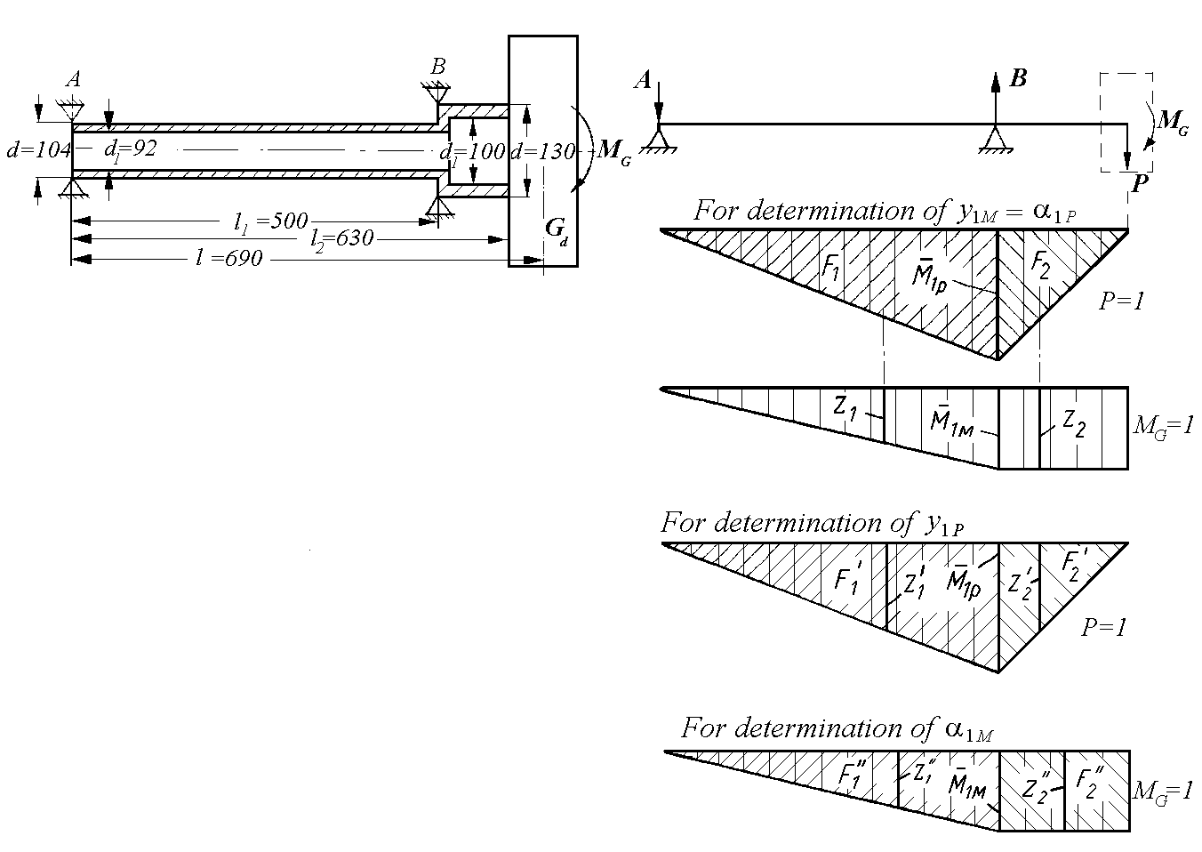
The design scheme and the indispensable sizes are shown in Fig. 8.30. To simplify, without large inaccuracy we obtain l2=1.
The rotor critical angular velocity is determined with the help of an equation (8.12):
.
Influence coefficients are determined, using Vereshchagin’s rule. For this purpose we segment the shaft and construct the diagrams of bending momenta caused by force Р=1 (at МG=0) and bending moment МG =1 (at Р=0).
1. The compiling of bending momenta equations and construction of diagrams.
The bending moment under a support, caused by concentrated singular force P=1 N, is equal to:
The bending moment, caused by a singular gyroscopic moment, on a console shaft segment is constant and equals МG = 1 Nm.
a b
Fig. 8.30. Example of rotor critical rotational speed determination:
a – scheme of a rotor; b – design scheme and diagrams
2. Determination of influence coefficients by Vereshchagin’s rule.
The sag, caused by a singular moment action, and the turn angle of shaft section, caused by a singular force action, are equal to:
where
The sag, caused by a singular force action, is equal to:
where
The turn angle of shaft section caused by a singular moment action is equal to:
where
3. Determination of critical angular velocity taking into account gyroscopic moment influence.
From equation (8.12) we have:
For direct synchronous precession the disc moment of inertia is equal to:
Then,
Hence
or
As we can see, rotor critical rotational speed is less than rotor operational rotational speed (n=12300 r/min) and less than rotor rotational speed at an idle rating (ni =10400 r/min). Therefore, the shaft of the given rotor is flexible.
The rotor operational rotational speed margin is equal to:
The rotational speed margin at an idle is equal to:
The rotor critical rotational speed taking into account support elasticity (according to experimental data) ncr=3750 r/min, i. е. it is 2,18 times smaller, than for a rotor on absolutely rigid supports.
The rotor critical rotational speed disregarding influence of gyroscopic moment and in the conjecture of shaft weightlessness is equal to (by the formula (8.5а)):
where
Thus, gyroscopic moment has caused increase of rotor critical rotational speed by
which has reduced a critical rotational speed margin.
8.8. Measures taken to reduce intensity of rotor oscillation connected with critical rotational speeds
GTE rotating rotor can be affected by various forces, damping oscillations. They include, first of all, friction forces in bearings, friction forces of rotor elements about operating environment, internal friction forces in the shaft material and other. These forces create a moment of resistance to rotation. The redundant turbine torque overcomes it, but it does not influence a shaft sag value. Besides, these forces hinder the shaft precession motion, and, therefore, promote its sag decreasing.
The shaft sag decreasing at operating ratings is also promoted by initial eccentricity decreasing. It is reached by good rotor balancing.
However, high accuracy of rotor initial balancing, i.e. balancing during manufacturing and repair does not solve all problems, since at long operation the unbalance value increases, which affects shaft sags at critical rotational speeds.
Therefore, the various design measures are taken at a design stage of the GTE. They must reduce the shaft sag at a critical rotational speed, and also change the value of critical rotational speed.
So, the critical rotational speed increases with increase of support casings and shaft rigidity at bending at the expense of the shaft diameter and cross-section area increase or intermediate support addition.
The reduction of a critical rotational speed is reached at the expense of shaft rigidity decreasing at bending, and also support elastic yielding increase, for example, by use of elastic rings placed between support casing and fixed bearing race, or at the expense of application of elastic bearing bushings like a “squirrel cage” in a support design (they will be considered in Chapter 11).
The shaft sag reduction at a critical rotational speed is provided with oil or band-oil dampers. The oil dampers in a combination with elastic elements promote safe transition through a critical rotational speed at engine start-up and cut-off.
Such complex of design and technological measures at the GTE rotors and their supports development provides reliable and safe engine operation within the whole range of operational ratings.