

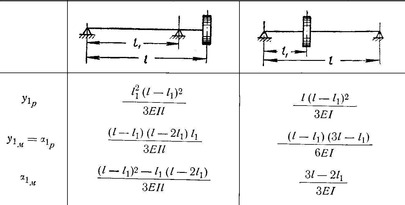
Table 8.1
Values of the influence coefficients
8.7.2. Reduction of a real flexural system to equivalent computational
To facilitate rotor critical rotational speed determination a real system with composite mass distribution, as well as elastic elements, is substituted by a simpler, dynamically equivalent system, consisting of elastic weightless shaft and discs, fixed on it.
The reduced localized masses, inertia momenta of these weights and rigidity (yielding) of separate element of an equivalent system are selected such that the normal mode frequencies and forms of an equivalent system do not differ from normal mode frequencies and forms of a real system.
The multi-supported engine rotor consisting of compressor and turbine rotors, jointed by coupling muff, is disjointed on separate double-support compressor and turbine rotors. The rotors interference on their critical rotational speeds depends on design and location of rotors coupling with regard to a support (see Fig. 8.18…Fig. 8.27). For example, at hinged coupling (see Fig. 8.19…Fig. 8.22, Fig. 8.24…Fig. 8.27) this influence is much less, than at rigid coupling (see Fig. 8.18, Fig. 8.23).
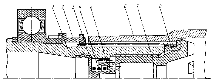
Fig. 8.18. Coupling muff of three‑supported TPE rotor:
1 – compressor shaft; 2 – distance sleeve; 3 – latch casing; 4 – latch spring; 5 – latch double-spline bushing; 6 – turbine shaft; 7 – coupling bolt; 8 – bolt bearing
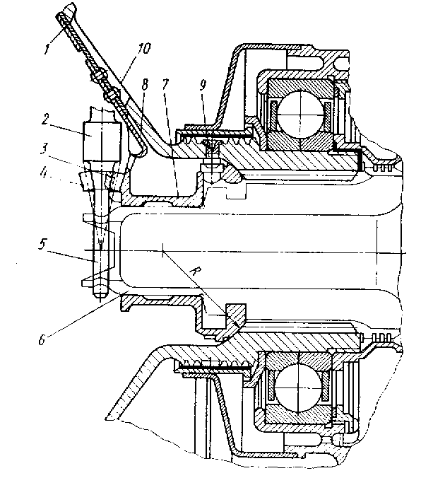
Fig. 8.19. Coupling muff of three‑supported TPE rotor:
1 – spring; 2 – toothed wrench; 3 – muff toothed sector; 4 – conical teeth on the wrench; 5 – wrench guide; 6 – turbine rotor; 7 – muff; 8 – detent for muff plugging; 9 – pin; 10 – window in compressor rotor journal for wrench input-output
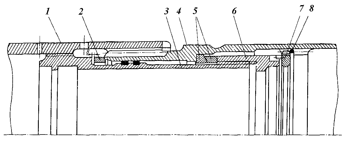
Fig. 8.20. Coupling muff of TFE high pressure rotors:
1 – compressor shaft; 2 – adjusting ring; 3 – intermediate thread bushing; 4 – turbine shaft; 5 – spherical rings; 6 – coupling bolt; 7 – split retaining ring; – axial clearance between shafts
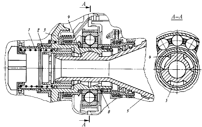
Fig. 8.21. Coupling muff of three‑supported helicopter TShE rotors:
1 – spring; 2 – double-spline moving bushing; 3 – rear journal of compressor rotor; 4 – bulge; 5 – turbine rotor journal; 6 – groove (slot)
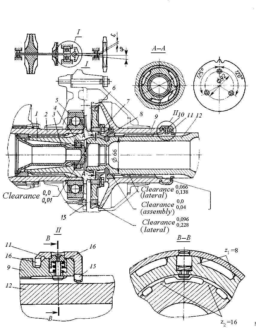
Fig. 8.22. Coupling muff of three‑supported TShE rotors:
1 – driven spline muff; 2 – compressor rotor journal; 3 – bolt; 4 – nut; 5 – support bearing; 6 – splines; 7 – scews-pins; 8 – flange; 9 – transitional driving muff; 10 – detent; 11 – retaining ring; 12 – turbine rotor journal; 13 – oil jet; 14, 15 – splines; 16 – detent
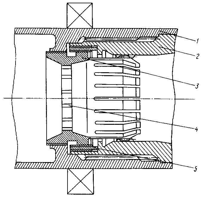
Fig. 8.23. Coupling muff of three‑supported TJE rotor:
1 – rear journal of compressor rotor; 2 – turbine shaft; 3 – coupling bolt; 4 – coupling bolt grooves; 5 – turbine shaft thread bushing
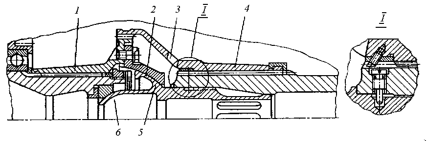
Fig. 8.24. Coupling muff of three‑supported TJE rotor:
1 – muff driven part; 2 – spherical surface, taken an axial force, directed to turbine; 3 – passage for oil support to muff cavity; 4 – muff driving part; 5 – stem; 6 – spherical surface, taken an axial force, directed to compressor
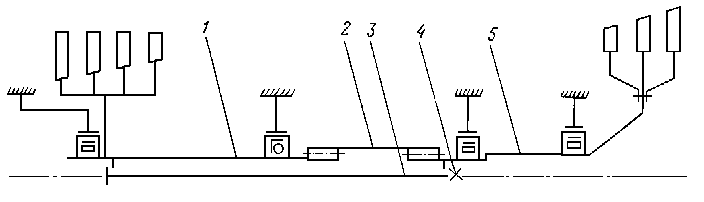
Fig. 8.25. Line diagram of four‑supported rotor coupling muff:
1 – compressor shaft; 2 – long spline shaft; 3 – flexible coupling bolt; 4 – nut of coupling bolt; 5 – turbine shaft
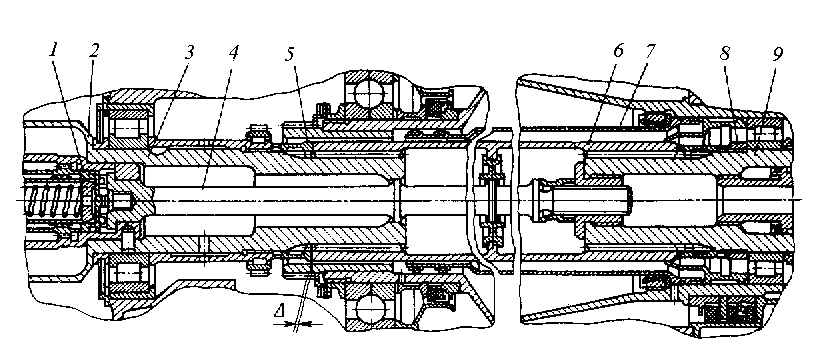
Fig. 8.26. Coupling of turbine and compressor shafts with the help of tubular
spring and tightening bolt (rod):
1 – lock; 2 – low pressure compressor shaft; 3 – low pressure compressor rotor rear journal; 4 – tightening bolt; 5 – lock bushing; 6 – tubular spring; 7 – thin-walled tube; 8 – nut; 9 – turbine shaft
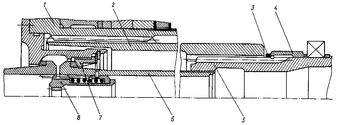
Fig. 8.27. Coupling muff of four‑supported TFE rotor:
1 – compressor shaft; 2 – spline shaft-tube; 3 – adjusting ring; 4 – distance sleeve; 5 – spline turbine shaft; 6 – coupling bolt; 7 – spherical support; 8 – lock
The number of localized weights and their arrangement on the shaft are selected according to arrangement of weights in a real system. The dispersed weights of the shaft, drum and other elements result in one or several weights of an equivalent system, which are often added to discs weights.
At transition from the real system to the equivalent system the number of freedom degrees will decrease and be equal to the number of localized weights. The shaft weights reduction taking into account only first bending oscillation form is considered below.
Reduction of weights. The values of equivalent system weights are determined from the requirement of kinetic energies equality of real and equivalent oscillating systems. For this purpose the shape of an elastic line is set, which is approximately accepted as an elastic line of an equivalent system.
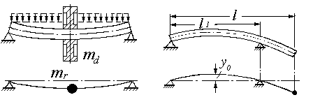
As an example we will consider the weights reduction of the double-support shaft with the disc in the middle (Fig. 8.29, a).
The kinetic energy of the oscillating real shaft with distributed load is equal to:
![]()
a b
Fig. 8.29. Scheme of weights reduction:
a – double-support shaft with disc in the middle; b – console shaft
For
![]()
the maximum value of shaft kinetic energy is equal to:
![]() (8.14)
(8.14)
Here l is length of the shaft; is density of shaft material; F is shaft cross-sectional area; p is frequency of shaft normal mode bending oscillations; уi is the centre of gravity displacement of shaft oscillating section corresponding to х coordinate.
Let the shape of an elastic line be determined by relation
![]() (8.15)
(8.15)
where y0 is sag in the middle of the shaft.
Having substituted (8.15) in the formula (8.14) and having made an integration, we will get:
![]()
But
![]()
Then
![]() (8.16)
(8.16)
The maximum kinetic energy of the equivalent reduced shaft with a reduced mass in the middle is equal to:
![]() (8.17)
(8.17)
The maximum kinetic energy of the disc arranged in the middle of the shaft is determined with the help of expression:
![]() (8.18)
(8.18)
Equating the expressions for kinetic energies, we will get:
![]()
From here we will get an expression for shaft reduced localized mass with the disc arranged in the middle between supports:
![]() (8.19)
(8.19)
In case, when the disc is asymmetrically arranged concerning the supports the point of disc location, as a point of shaft weight reduction is also taken. Let in a point of reduction arranged in distance х from a support, the maximum sag be y. Then, the maximum kinetic energy of a reduced mass is equal to:
![]()
The maximum kinetic energy of the shaft is equal to:
![]()
Comparing the two latter expressions, we will get:
 (8.20)
Relation
 (8.21)
is called a reduction coefficient of shaft weight.
Console shaft weight (Fig. 8.29, b) is reduced in the same way as the shaft weight with the disc asymmetrically arranged concerning supports. The point of disc location is taken as the point of reduction.
Equation of parabola can be taken as an equation of such shaft elastic line:
where l1 is distance between shaft supports; х is a moving coordinate along shaft length.
The reduced localized mass of the console shaft is equal to:
![]() (8.22)
(8.22)
The shaft weight of a multi-disc double-support rotor is normally added to the weight of one of the discs. If the shaft weight makes a small part of rotor total mass, the shaft influence can be neglected.
Reduction of inertia momenta. A mass inertia moment of the composite shape disc with elements, abutting to it, (flanges, clamps, etc.) is determined as the total of inertia momenta of the elementary bodies of revolution, this disc can be segmented into.
The total disc polar moment of inertia is equal to:
![]()
where n is the number of elements, the disc is segmented into.
The equatorial moment of disc element inertia concerning diameter passing through an element weight centre, is equal to:
![]()
The equatorial moment of disc inertia concerning diameter passing through a disc weight centre, is determined from the formula
![]()
where mi is weight of i-th element; хi is distance between weight centre of i‑th element and disc weight centre or reduced disc mass.
The mass reduced inertia moment of rotor blades fixed on the disc, is determined similarly.
The polar inertia moment of rotor blades assembly is equal to:
![]() (8.23)
(8.23)
where zb is the number of rotor blades in a rotor wheel; mb is mass of one blade; rc is distance between blade airfoil weight centre and rotation axis.
If the strength of a blade is calculated, the distance between blade airfoil weight centre and rotation axis can be determined from the formula (see Fig. 3.1)
![]()
The equatorial inertia moment of blades concerning diameter, passing through disc weight centre, is equal to:
![]() (8.24)
(8.24)
where xc is distance between blade assembly weight centre and disc weight centre (or reduced mass of discs) along rotor axis.
Finally, we will get for the whole rotor:
 (8.25)
where n is the number of blades assemblies, whose momenta of inertia are reducted to the given disc or to reduced mass of discs.
The equatorial inertia moment of thin discs is equal to:
![]()
For impellers of centrifugal compressors it is equal to:
![]()