

Fig. 8.12. Static elastic anisotropy of a casing
The dynamic anisotropy of casings results in qualitatively new futures of design dynamic “behavior”. First of all, they are:
- “lamination” of each rotor critical rotational speed into two speeds, corresponding to visualization of two resonant conditions at two different rotor rotational speeds in two mutually orthogonal meridional planes;
- design precessing (which will be considered later) becomes non‑regular, i. е. its points (during oscillations) travel along elliptical, instead of circular trajectories.
The typical future of casing dynamic “behavior” near some rotor critical rotational speed laminated into two speeds is shown in Fig. 8.13 (qx and qy are projections of precessing radius onto x and y axes, respectively). This capability should always be taken into consideration and, especially, at measuring and control of engine vibrational condition.
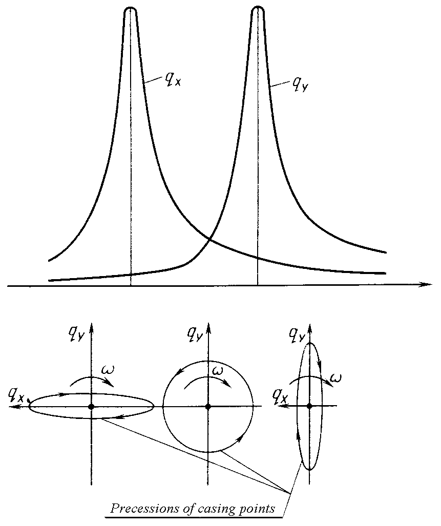
Fig. 8.13. Nature of casing dynamic “behavior” near a rotor critical rotational speed
at casing anisotropy (lamination of a critical speed)
Clearances in bearings. Under action of gravity or other static loads the radial clearances in bearings are cardioidly taken out, that is equivalent to increase in casing dynamic anisotropy. At the same way we will note, that for fast-running rotors under action of their unbalance the running rating is possible (when the unbalanced forces exceed rotor gravity). The rotor “floats”, thus its unbalance and, accordingly, the vibrations of the engine increase sharply. The radial clearances in bearings are not made zero because of their broad temperature deformations span which are capable of resulting (at insufficiency of the clearances) in jamming of solids of revolution and destruction of bearing.
The torque transmitted by rotor reduces a rotor critical rotational speed because it creates the effect of decreasing its rigidity.
For GTE rotors the critical rotational speed decrease does not exceed 2...5 %. The rotor critical rotational speed is determined with correction for the value of transmitted torque by the formula
where ncr is a design rotor critical rotational speed without taking into account transmitted torque; Мcr = 2EJ/L is a critical torque, under action of which the shaft loses its stability.
Influence of axial forces. When engines work their shafts are stretched by large efforts caused by gas forces and affixed in opposite directions to compressor and turbine rotors. It promotes increase in cross-sectional rigidity of shafts, resulting in some augmentation of normal mode frequencies of system and, accordingly, of critical rotational speeds of rotors. This influence can be noticeable for rotors with rather lengthy shafts of small diameter (for example, for low-pressure spool rotors of multi-shaft TFEs). With change of flight rating, gas forces change and critical rotational speeds of rotors change also.
The axial force influence on the value of critical rotational speed of GTE shaft is insignificant and makes 1...3 %. The stretching load increases and squeezing load reduces a critical rotational speed at the expense of effect of a shaft rigidity change at bending.
Rotor critical rotational speed with correction for the value of axial force is calculated by the formula:
![]()
where Р is an axial force which affects the shaft; Рcr is a critical force, under action of which the shaft loses its stability.
For shaft with non-fastened ends
![]()
For shaft with fastened ends (when coupling bolts and bars for compressor and turbine discs coupling are used)
![]()
Influence of gyroscopic moment on critical speeds of rotation. The gyroscopic moment rather essentially influences on value of critical speed of rotation, specially with increase in its order.
The bent shaft under action of its own weight and weight of discs, fixed on it, rotates concerning its curvilinear axis (elastic line) at angular velocity r (Fig.8.14). If elastic line of the shaft is immovable, the absolute angular velocity of shaft rotation is equal to angular rotational velocity r.
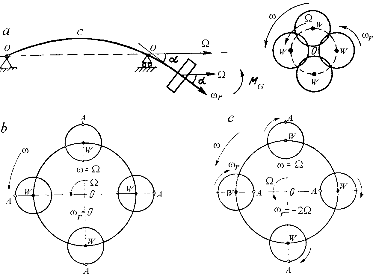
Fig. 8.14. Precession motion of a rotor:
а – general case; b – direct synchronous precession; c – retrograde synchronous precession
When disturbing forces act the shaft elastic line can begin to rotate about its direct geometrical axis OO (bearings axis) with a transportation velocity . The motion of elastic line concerning a bearings axis OO (rotation of a plane, in which the curved axis of a shaft lies) is called precession motion (precession). In this case the motion of the shaft is the total of two motions: relative motion with angular velocity r (concerning an elastic line of the shaft), and transportation motion with angular velocity (rotation of shaft elastic line about its direct geometrical axis OO ). The absolute speed of rotor rotation is equal to:
![]() (8.6)
(8.6)
When elastic line of a shaft rotates making some angle with an undeformed axis in landing area of the disc, a gyroscopic moment appears, acting in a plane of vectors angular velocities r and . The gyroscopic moment aims to turn rotor so that the directions of relative velocity vector r and angular velocity vector of precession to coincide.
The vector of gyroscopic moment is perpendicular to the plane of vectors of angular velocities r and . It is known from theory of the gyro, that
![]() (8.7)
(8.7)
where Jр is a mass polar moment of disc inertia concerning axis of its rotation; Je is a mass equatorial moment of disc inertia concerning its diameter.
Since angle α is small it is possible to accept sin=, соs=1 and instead of the geometrical total of the angular velocities the algebraic total =r+ can be taken.
Then
![]()
or
![]() (8.8)
(8.8)
Such precession motion, when the absolute angular velocity of rotor rotation is equal to transportation angular velocity (=), is called direct synchronous precession or simply direct precession. In this case
![]()
The minus sign before a bracket means, that the gyroscopic moment aims to reduce angle , resulting in increase in critical speed of shaft rotation.
At direct synchronous precession (Fig. 8.14, b) the sign of stress in any point of shaft section remains invariable with time (in point A the tensile stress acts at any position), i.e. all fibers of the shaft are loaded by constant bending moment and shaft cyclic deformation does not appear.
Precession motion, at which the absolute angular velocity of rotor rotation is equal and opposite by its sign to transportation angular velocity (= – ), is called as retrograde synchronous precession or simply retrograde precession. In this case (Fig. 8.14, c)
![]() (from
equality =r + )
(from
equality =r + )
![]()
The plus sign before a bracket means, that the gyroscopic moment aims to increase angle , resulting in lowering of critical speed of shaft rotation.
At retrograde synchronous precession the stress in any point of the shaft changes the sign with time. The shaft in this case is loaded by cyclical bending moment, at which friction forces in shaft material and in rotor elements connection places promote damping of cross-sectional oscillations. Therefore at retrograde synchronous precession the intensity of oscillations at a critical rotational speed is less than at direct synchronous precession. Taking this into account, at course and diploma projecting a critical rotational speed at retrograde synchronous precession may be not determined.
Any other ratios of angular velocities values and , giving accordingly other kinds of precession motion, are also possible. If the angular velocities of rotations and do not coincide (when angular velocities of shaft curved axis rotation plane and shaft do not coincide), the precession is called noncynchronous.
The direct precession usually takes place at rotor acceleration from a quiescent state and is caused by action of centrifugal forces of rotor unbalanced weights. The complex types of GTE shaft precession motion (both retrograde and nonsynchronous precessions) are the consequence of shaft cross-sectional oscillations with asymmetrical disc arrangement, as well as internal friction in the shaft material. They appear if there are any external disturbing forces. So, in the double-rotor engine the centrifugal force of one shaft can cause the retrograde precession motion of the other shaft which is a support for the first shaft.
Generally, formula (8.8) can be written this way:
![]() ,
,
where
for direct precession
![]()
for
inverse precession
![]()
As it was already mentioned, at direct precession the gyroscopic moment acts in the direction of angle and sag y decreasing, and consequently, it acts in the direction of rotor critical rotational speed increase.
At retrograde precession the gyroscopic moment acts in the direction of angle and sag y increase, and consequently, in the direction of rotor critical rotational speed reduction.
However rotation of a rotor at retrograde precession is less dangerous, than at direct precession, since during one revolution each shaft fiber is either stretched, or squeezed. It causes a large hysteresis in a material and fading of sags development. Therefore the retrograde precession is accompanied by small sags of the shaft even at critical speeds of rotation. At direct precession shaft fibers are not subjected to alternating stresses, therefore hysteresis is absent.
The fiber deformation behaviour at direct precession will change, if the force of weight acts or if the rigidity of rotor-casing system is different in different directions. In this case centre-of-gravity trajectory is an ellipse (see Fig. 8.12 and Fig. 8.13).