8.7. Operational factors affecting critical rotational speeds of gas turbine engine rotor
The change of shaft static sag shows how various factors can influence rotor critical rotational speeds. All factors increasing shaft sag result in reduction of its critical rotational speed. So, the reduction of a critical rotational speed is caused by increase in distance between supports, reduction of shaft rigidity, increase in localized masses weight, reduction of tightness of shaft hub landing in the bearing, etc.
The elasticity of supports causes the reduction of a rotor critical rotational speed. Its influence can be taken into account when calculating, increasing the main sag by the value of supports deformation under action of support reactions.
So, the additional shaft sag under the disc due to supports elasticity (Fig. 8.11) is equal to
![]()
Then the total shaft sag under the disc can be determined by the formula:
![]()
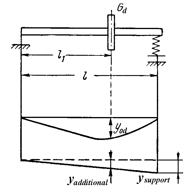
Fig. 8.11. Taking into account supports elasticity influence on rotor critical speeds
Varying support elasticity, rotor critical speeds can be changed within a wide range. It is often used to displace rotor critical speeds beyond the limits of operational speeds.
Calculation of rotor element yielding in case of discs pressing on the shaft (when divided shafts jointed by coupling muffs, flanges, and when load-bearing casing is of a composite form} is difficult, and the reliable input data of yielding to calculate rotor critical speeds can be obtained only experimentally.
To measure rotor yielding it is set on racks fasterned on the rigid basis, and sequentially is loaded in places of discs fastening with the help of hydraulic device or jack with dynamometer. Sags are measured by indicators with a multiplying factor 2…5 m, and turn angles – by optical device with mirror sensors fixed on discs.
The rotor yielding of modern turbine engine axial-flow compressors is insignificant and does not exceed (3…10)10–7 m / N.
When measuring casing yielding a support yielding (i. е. the shaft axis movement in the bearing concerning casing at unit load) and casing yielding (at it fastening in engine attachment fittings) are separately gauged.
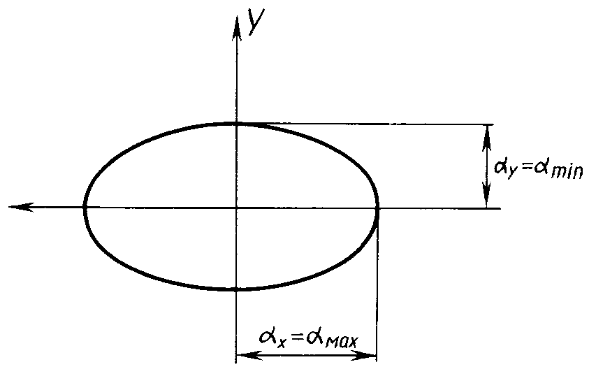
Anisotropy of casings. It was assumed above, that engine (as dynamic object) has a stringent axial symmetry. However the real designs always deviate from it to a greater or lesser extent. Such deviation can be more essential for stator design. It is caused (in addition to random reasons) by features of engine attachment fitting to an aircraft, asymmetry of massive aggregates arrangement on casings, etc.
Figure 8.12 shows the typical character of elastic radial static anisotropy of a casing corresponding to a bearing housing. Here the ellipse major semi‑axes of static yielding (αx and αy) are oriented in vertical and horizontal directions, which is typical of real designs. The static anisotropy also results in dynamic anisotropy of casings, as their weights are involved in oscillations. The value, ratio, and generally an angular orientation of major semi‑axes of ellipse of dynamic casing yielding depend on rotational speed of an exciter (of unbalanced rotor).