
- •Foreword
- •Предисловие
- •Chapter 1. Introduction
- •From the history of aeroengines development. Classification of air gas turbine engines
- •Table 1.1
- •Table 1.2
- •1.2. Design features of manifold types of gas turbine engines
- •Main specifications for some serial turboprop and turboshaft
- •Fig. 1.3. Principal scheme of a two-shaft afterburning
- •Fig. 1.4. Principal scheme of a two-shaft tfe
- •Fig. 1.5. Principal scheme of a three-shaft tfe
- •Fig. 1.8. Principal scheme of a tpfe with a coaxial propfan
- •Main stages of gas turbine engines creation
- •1.4. Absolute and specific parameters of gas turbine engines
- •1.4.1. Absolute and specific parameters of turbojet engines
- •1.4.2. Absolute and specific parameters of turboprop engines
- •I.5. Air gas turbine engine’s lives
- •1.5.1. Nomenclature of lives
- •1.5.2. Sequence of assigning, setting and increase of lives
- •1.5.3. General requirements to life testing of engines and their main elements
- •1.5.4. Forming of test cycles
- •1.5.5. Forming of programs of life tests
- •Questions for self-check
- •2.1. Types of loads acting upon gas turbine engine structural elements
- •2.1.1. Classification of loads
- •2.1.2. Gas loads
- •2.1.3. Mass (inertial) forces and momenta
- •2.1.4. Temperature stresses
- •Fig. 2.4. For determination of the centrifugal forces
- •Fig. 2.5. For determination of the disc temperature stresses
- •2.1.5. Concept of dynamic loads
- •Fig. 2.9. Gas flow velocity behind nozzle vanes
- •2.2. Axial gas forces coming into action in gas turbine engines. Formation of thrust in gas turbine engines of manifold types
- •2.2.1. Axial gas forces acting on the basic gas turbine engine units
- •Fig. 2.10. Scheme of axial forces acting on basic gte units
- •2.3. Determination of axial gas force acting on impeller of gas turbine engine centrifugal compressor
- •2.4. Torques coming into action in gas turbine engines. Balance of torques
- •In gas turbine engines
- •2.4.1. Torques in turbine and compressor
- •Fig. 2.14. For determination of turbine rotor wheel torque
- •2.4.2. Torque balance in gas turbine engines of manifold types
- •Questions for self-check
- •Engine blades
- •Loads acting on blades. The blade stressed state characteristic
- •Fig. 3.1. Loads acting on the blade (a) and the scheme of blade loading
- •Determination of rotor blade tensile stress caused by centrifugal forces
- •The design scheme
- •3.2.2. Equation of a rotor blade stressed state
- •Integrating equation (3.3) in view of the ratio (3.1), we will get
- •3.2.3. Calculation of tensile stress at manifold laws of change of blade section area along its length
- •If the blade section area decreases from the root to periphery under the linear law:
- •In this case an integration by formula (3.7) yields
- •Determination of rotor blade bending stress caused by gas forces
- •3.3.1. Design scheme of a blade
- •3.3.2. Determination of gas load intensities
- •Determination of the bending momenta in axial and circumferential planes
- •3.3.4. Determination of the blade section geometrical characteristics
- •Determination of bending stress caused by gas force
- •Determination of rotor blade bending stress caused by centrifugal forces
- •The design scheme
- •3.4.2. Equation of the bending momenta
- •3.5. Guide and nozzle diaphragm vanes strength calculation features
- •3.5.1. Console type vanes
- •3.5.2. Double-support vanes
- •3.5.3. Frame type vanes
- •3.6. Evaluation of gte rotor blades strength
- •3.6.1. Grounding of blade stressed state criterion
- •3.6.2. Estimation of the blade temperature
- •3.6.3. Determination of blade strength safety factor coefficients
- •Questions for self-check
- •4.1. Loads affecting discs
- •The design scheme and assumptions made at disc strength calculations
- •Fig.4.1. Design scheme of the disc
- •4.3. Design ratings
- •4.4. Disc thermal condition
- •4.5. The disc stressed state equation. Boundary conditions
- •4.5.1. An equilibrium equation
- •4.5.2. Equation of deformations generality
- •4.5.3. Determination of stresses in rotating, unevenly heated elastic disc with an arbitrary profile
- •Fig. 4.2. Elementary disc forms
- •Fig. 4.3. Discs of arbitrary profiles
- •4.5.4. The procedure of the arbitrary profile disc stresses calculation
- •4.6. Disc durability criteria and safety factor coefficients
- •4.6.1. Selection of the stressed state criteria
- •4.6.2. Disc safety factor coefficients
- •Integrating an equilibrium equation, we find
- •4.7. Features of strength calculation of centrifugal compressor and radial-inflow turbine discs
- •The weight of the carrier disc for a chosen ring makes
- •Fig. 4.5. Design scheme and character of the radial and circumferential stresses change along radius of two-sided impeller of centrifugal compressor
- •4.8. Peculiarities of stresses calculation in drum-and-disc designs
- •Fig. 4.6. Design scheme of a drum-and-disc rotor
- •From here
- •Questions for self-check
- •Chapter 5. Static strength of gas turbine engine shafts
- •Loads acting on shafts
- •Design schemes and stressed state of shafts. Safety factor coefficient estimation
- •In an axial direction the shaft tensile (compressive) stresses are equal to
- •The shaft static strength is estimated by a safety factor coefficient value
- •Questions for self-check
- •Chapter 6. Dynamic strength of gas turbine engine blades
- •6.1. Vibrations of blades and forces causing vibrations
- •6.2. Kinds and forms of blade normal modes
- •Fig. 6.3. Flexural vibration modes of rotor blades
- •Fig. 6.4. For rotor blade normal mode frequency definition
- •6.3. Normal modes of blades with a stationary cross-section area
- •6.4. Normal modes of blades with a variable cross-section area
- •6.5. Influence of blade attachment effort to the disc
- •6.6. Influence of centrifugal forces on blade vibration frequency
- •F ig. 6.7. Determination of blade dynamic normal mode frequency
- •Influence of variable temperature
- •6.8. Forces damping blade vibrations
- •6.9. Resonant modes of the blade vibrations. The frequency diagram
- •F ig. 6.8. Example of turbine rotor wheel frequency diagram
- •6.10. Torsional and composite blade vibrations
- •6.11. Elimination of blade vibrational breakages
- •6.12. Concept of blades self-oscillations
- •Versus vibration amplitude
- •Questions for self-check
- •Chapter 7. Dynamic strength of gas turbine engine discs
- •General information
- •Forms of disc normal modes
- •Wave linear speed equals
- •Disc normal mode frequency
- •The compressor and turbine rotor wheel vibration calculation
- •Factors influencing the disc normal mode frequency
- •Disc forced undulations
- •The ways to eliminate dangerous resonance oscillations of rotor wheels
- •Questions for self-check
- •Chapter 8. Critical rotational speeds of gas turbine engine rotor
- •8.8. Measures taken to reduce intensity of rotor oscillation connected with critical rotational speeds.
- •Concept of critical rotational speeds of gas turbine engine rotor
- •Critical rotational speed of the two-support weightless shaft with disc
- •Fig. 8.8. Value of shaft static sag for different rotor schemes
- •Fig. 8.9. To the problem of a rotated rotor stability in a subcritical area
- •Connection of rotor critical rotational speed with its
- •Concept of two-support rotor critical rotational speeds of higher order
- •Critical rotational speed of the two-support ponderable shaft without disc
- •8.6. Critical rotational speeds of the ponderable shaft with several discs
- •8.6.1. Method of decomposition into elementary systems
- •8.7. Operational factors affecting critical rotational speeds of gas turbine engine rotor
- •Fig. 8.11. Taking into account supports elasticity influence on rotor critical speeds
- •Fig. 8.12. Static elastic anisotropy of a casing
- •Determination of critical rotational speeds taking into account
- •Influence of gyroscopic moment
- •Table 8.1
- •Values of the influence coefficients
- •8.7.2. Reduction of a real flexural system to equivalent computational
- •Example of rotor critical speed calculation
- •The rotor operational rotational speed margin is equal to:
- •The rotational speed margin at an idle is equal to:
- •8.8. Measures taken to reduce intensity of rotor oscillation connected with critical rotational speeds
- •Questions for self-check
- •8.7. What is dependence of rotor critical rotational speed on its cross-sectional oscillation frequency?
- •Of gas turbine engine shell designs
- •9.1. Shell strength calculation
- •Fig .9.1. Design scheme of a shell
- •9.2. Stability of cylindrical and conical shells
- •9.3. Vibrations of cylindrical shells
- •Questions for self-check
- •Chapter 10. Control of gas turbine engine
- •Vibration state
- •10.2. Control of gas turbine engine vibrations
- •10.3. The ways to lower the vibration level of gas turbine engines
- •10.3.1. The procedures of vibration level lowering at stage of designing
- •10.3.2. The procedures of the vibration level lowering at production stage
- •Fig. 10.3. Scheme of the rotor static balancing
- •Fig. 10.4. Scheme of the rotor dynamic balancing
- •Will be compensated by centrifugal force of balanced elements weights
- •10.3.3. The procedures of the vibration level lowering at maintenance stage
- •Questions for self-check
- •Сhapter 11. Gas turbine engine rotor supports
- •11.1. Brief data about gas turbine engine rotor supports
- •Fig. 11.3. Scheme of gte rotor support
- •11.2. Calculation of support bearings
- •Fig. 11.9. Ball bearing:
- •For roller bearings we use the formula
- •11.2.2. Estimation of the bearing safe life
- •11.2.3. Check of the bearing high-speed
- •11.2.4. Check of the bearing static load-bearing capacity
- •11.2.5. Definition of the necessary oil circulation through the bearing
- •Questions for self-check
1.2. Design features of manifold types of gas turbine engines
Gas turbine engines can be of different designs. They differ both in relative position of the main engine units and accessories arrangement, that is layout, and units design. Generally, the GTE design of manifold types is selected taking into account the designation and requirements made of the engine.
Table 1.3
Main specifications for some serial turboprop and turboshaft
engines used in civil aviation
Engine |
Country |
Takeoff rating power N, kW |
Efficient fuel con-sumption Ce, kg/(kWh) |
Com-pressor pres-sure ratio *c |
Mass air flow rate Ga, kg/s |
Turbine inlet tempe-rature Т*ti, К |
Mass of engine Meng, kg |
ТГД-10 |
USSR |
736,0 |
0,340 |
7,4 |
4,1 |
1270 |
225 |
ТГД-20 |
USSR |
1100,0 |
0,330 |
9,5 |
5,9 |
1270 |
360 |
АИ-24Т |
USSR |
2075,0 |
0,340 |
7,7 |
14,4 |
1200 |
600 |
АИ-20М |
USSR |
3200,0 |
0,330 |
8,5 |
21,0 |
1200 |
1000 |
НК-12МВ |
USSR |
11000,0 |
0,280 |
9,7 |
49,5 |
1200 |
2950 |
ГТД-350 |
USSR |
258,0 |
0,480 |
6,0 |
2,5 |
1228 |
175 |
ТВ2-117А |
USSR |
1100,0 |
0,360 |
6,6 |
8,2 |
1150 |
330 |
ТВ3-117 |
USSR |
1840,0 |
0,340 |
8,5 |
9,2 |
1300 |
300 |
Д-136 |
USSR |
8700,0 |
0,300 |
17,5 |
55,0 |
1400 |
1000 |
GT7-5 |
England |
912,0 |
0,330 |
7,5 |
5,5 |
1370 |
307 |
PT-7A |
Canada |
1026,0 |
0,360 |
9,0 |
6,5 |
1250 |
500 |
T55L-9 |
USA |
1860,0 |
0,376 |
6,4 |
9,7 |
1400 |
620 |
T56A-7 |
USA |
2980,0 |
0,330 |
9,5 |
15,0 |
1243 |
846 |
T53L-13 |
USA |
1130,0 |
0,357 |
7,4 |
5,8 |
1200 |
240 |
T55L-5 |
USA |
1620,0 |
0,358 |
6,3 |
8,7 |
1250 |
258 |
T-700-68 |
USA |
1147,0 |
0,307 |
17,0 |
4,5 |
1473 |
235 |
The turbojet engines structurally differ in such characteristic features as: the type of compressor and turbine, the number of rotors, means of thrust augmentation, inlet and exhaust arrangement types.
Single-rotor
TJE
with subsonic
inlet,
axial-flow or centrifugal compressor and without afterburner is an
engine of an elementary scheme, which is used on aircraft with
subsonic
flight speeds.
The inlet
of such engines functions as a channel, that supplies air to the
compressor without considerable transformation of air
kinetic energy
into pressure
potential energy.
The compressor can be of axial-flow or centrifugal type depending on
the required value of air pressure ratio. The principal scheme of TJE
with the axial-flow compressor is shown in Fig. 1.1. and the
principal scheme of the TJE with the centrifugal compressor is shown
in Fig. 1.2. The combustion chambers are tubular
(“can”),
annular
or cannular
(“can”-“annular”). The gas turbine has one or two stages.
A nozzle,
as a rule, is of a
constant geometry.
The arrangements
of
sound
suppression
and thrust
reversing
can be placed in an exhaust
arrangement.
They are used for decreasing an airplane
roll-out
after landing
as well a
s
for noise abatement.
Fig. 1.1. Principal scheme of TJE with an axial-flow compressor
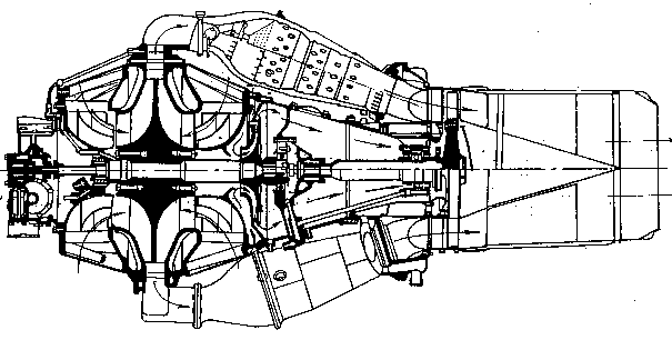
Fig. 1.2. Principal scheme of TJE with a centrifugal compressor
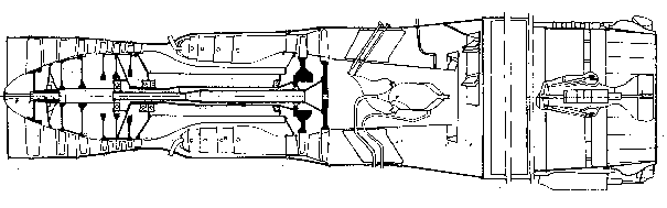
The augmented ATJE (Fig. 1.3) has an afterburner, located behind the turbine. In the afterburner the additional fuel is burnt to increase engine thrust for a short time. The ATJE nozzle is a variable to provide an augmented turbojet engine afterburning rating, to facilitate the engine starting, and also to increase the engine efficiency and profitability in flight.
Depending on the number of rotors, TJEs are subdivided into single- and two-shaft. Two-shaft ATJE (Fig. 1.3) has two consecutive compressor spools of low and high pressure, which rotate with the help of kinematically independent turbines.
Such layout has a number of important advantages. There is no unstable compressor operation in case engine rating deviates from designed one due to “rotors slip”. Thus, the absence of mechanical connection between rotors permits a more flexible engine control under the optimal laws. It is enough to crank only high pressure rotor for engine starting, and due to this the required starter power and starting time of the engine are reduced. The two-shaft engine is structurally more composite than single-shaft engine because of the greater number of supports, shafts, couplings and more complex lubricating system.