

Disc forced undulations
It was shown above, that oscillations of the disc with nodal diameter fixed concerning the disc can be considered as the total of two waves which are travelling in opposite directions with identical angular velocity and amplitude.
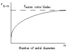
Fig. 7.7. Character of rotor wheel normal mode frequency change depending on
the number of nodal diameters
At disc rotation a system of excitation, which will support only one travelling wave, can be set. As an example we will consider the rotation of small rigidity disc (of rubber disc), undulating in an air medium (flag oscillations).
At air streamlining wave crests and cavities the appearing difference of pressure will support the sag of disc rim. Thus, the velocity of air streamlining wave crests and cavities in case of wave travelling forward (direct wave) (Fig. 7.8, а) is equal to:
![]()
and in case of wave travelling backward (back wave, backward wave, return wave, reverse-travelling wave) (Fig. 7.8, b)
![]()
where d, dw, bw are the angular velocities of disc, waves travelling forward and backward, respectively.
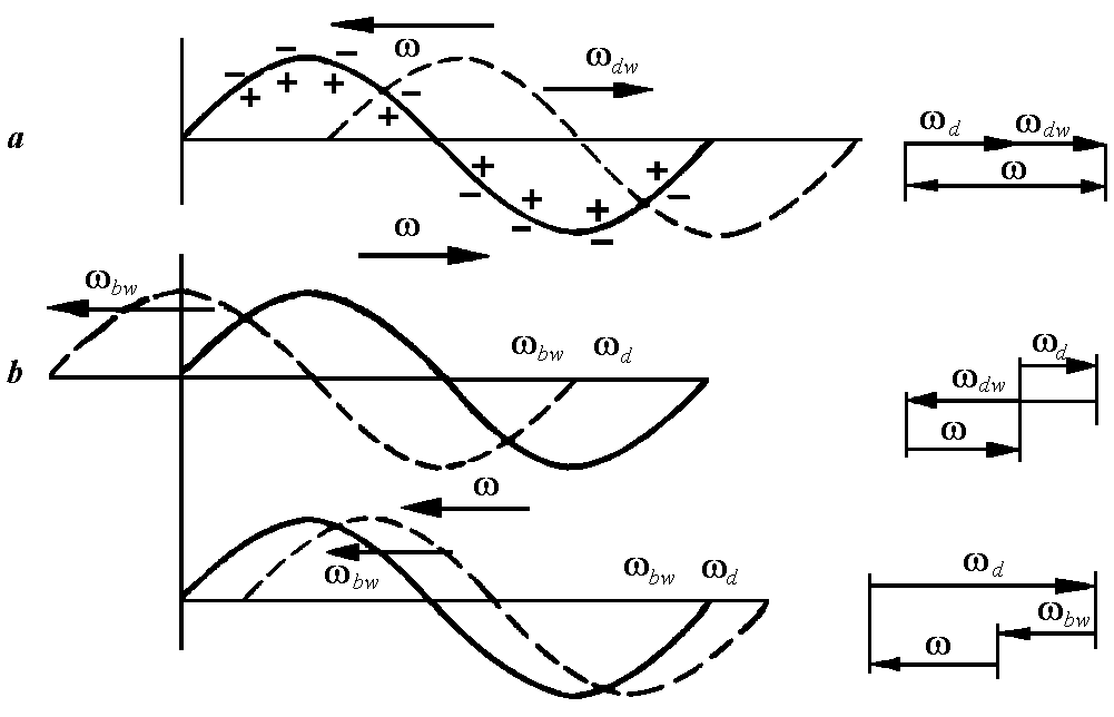
Fig. 7.8. Forced undulations of the disc:
a – forward (direct) travelling wave; b – backward travelling wave
In relative motion the direction of velocity of air streamlining wave crests and cavities, can coincide with direction of travelling waves or be opposite. In first case the travelling waves are supported, in the latter they are suppressed (are damped). Therefore, when streamlining crests and cavities travelling wave forward the flow counteracts wave motion and the wave is damped.
When crests and cavities of the wave travelling backward are streamlined at bw>d the flow counteracts wave motion and it is damped. If bw<d, the streamline direction coincides with direction of waves travelling backward and the wave is "urged on", with the oscillations supported.
With regard to stationary observer with number of waves m in each chain the frequencies of waves travelling forward and backward are equal to
![]() ,
,
respectively.
If the velocity of propagation of wave travelling backward is equal to disc rotational speed ns, the standing wave will be generated concerning the stationary observer. This can take place, when the constant fixed force acting on the disc (Fig. 7.9) performs positive work, as its direction coincides with disc deformation direction in the point of its application. The accumulation of energy and increase in disc rim sag take place.
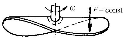
Fig. 7.9. Constant fixed force acting on the disc
Most dangerous is the case, when the number of exciting constant fixed forces Р is equal to the number of nodal diameters m, with distance between application points of these forces being equal to wave length (Fig. 7.10).
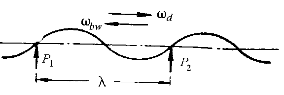
Fig. 7.10. Regarding to problem of disc critical speed
The disc rotational speed equal to velocity of backward travelling wave motion is called critical speed of the disc. In this case fbw=fd ‑mns cr=0 (“standing wave”). The corresponding to disc critical speed the rotor critical rotational speed is equal to:
![]()
The rotor critical rotational speed should be beyond the bounds of rotor operation rotational speed of rotor.
It is recommended that engines have a reserve of rotor critical rotational speed
![]()
at number of nodal diameters m:
m=2 n 15 %;
m=3…4 n 10 %;
m=5…6 n 7 %.
Changing disc normal mode frequency (at m=2…3 – changing disc hub thickness; at m4 – removing material from disc lateral surfaces near the rim) or changing disturbing force harmonics order, we can tune out from resonance and critical rotational speeds of rotor.
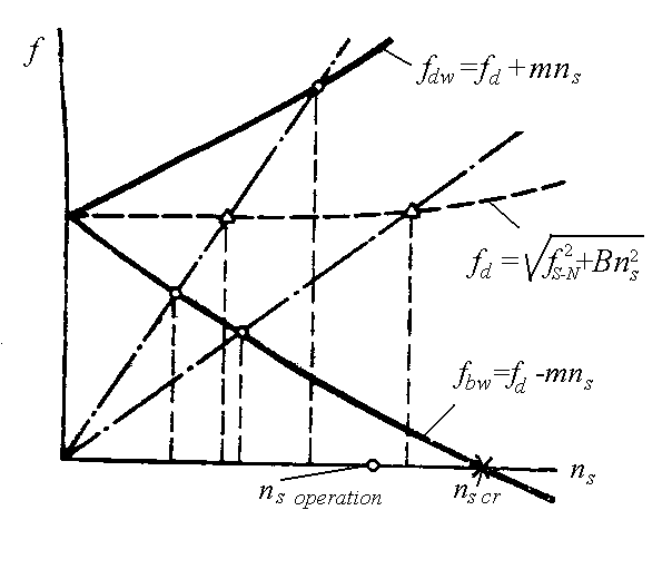
Fig. 7.11. Frequency diagram of the rotated disc
The probable resonance and disc critical speeds are determined with the help of disc frequency diagram (Fig. 7.11). On this diagram depending on rotor rotational speed the harmonics of disturbing forces, the disc dynamic normal mode frequencies and frequencies of waves travelling forward and backward are marked. The crosspoints of straight lines of frequencies of disturbing forces with frequency curves of waves travelling backward and forward correspond to resonance rotor speeds. The crosspoint of wave frequency curve travelling backward with an axis of abscissas defines the critical speed of the disc.