

Versus vibration amplitude
The plane-parallel blade self-oscillations provide the simplest example of self-oscillations of an aerodynamic system.
T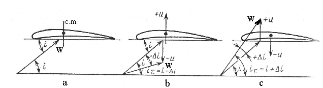 o
make things simpler, we shall consider that the separate profile
oscillates in direction perpendicular to chord of the profile at
which the profile makes reciprocating
motion.
Let profile with a velocity U
up
at the considered moment (Fig. 6.12, b).
Then the
effective angle of incidence i
will be decreased by i.
o
make things simpler, we shall consider that the separate profile
oscillates in direction perpendicular to chord of the profile at
which the profile makes reciprocating
motion.
Let profile with a velocity U
up
at the considered moment (Fig. 6.12, b).
Then the
effective angle of incidence i
will be decreased by i.
Fig. 6.11. Scheme of aerodynamic damping, angle of incidence and
relative velocity formation
a – at non-oscillating blade; b – decrease in blade angle of incidence at its motion to convex profile side with velocity +U; c – increase in blade angle of incidence at its motion to its concave side with velocity –U
The angle of incidence decrease will take place in all cases of profile moving up. When it goes down effective angle of incidence is augmented.
I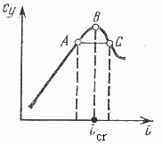 t
is a typical case of aerodynamic damping.
However at supercritical blade flow
(Fig.6.12) the work of periodic force, which is the result of
oscillations, will be directed when these oscillations are supported.
t
is a typical case of aerodynamic damping.
However at supercritical blade flow
(Fig.6.12) the work of periodic force, which is the result of
oscillations, will be directed when these oscillations are supported.
6.12. Lift coefficient versus angle of incidence Cy=f()
Thus, oscillations arisen for some random reasons will rise as long as damping work equals excitation work.
Therefore, the appearance of self-exciting blades oscillations, that is self-oscillations is possible in case of blade profiles supercritical flow.
Such self-oscillations at modes of supercritical flow are quite often in reality. For their elimination it is necessary to reduce angle of incidence and make it smaller than icritical angle is at oscillations.
Blades self-oscillations can also be eliminated by application of blade antivibrational caps, located in an airfoil section.
Questions for self-check
1. Name kinds and forms of blade normal mode.
2. How can a normal mode frequency of blades with constant cross-section area be calculated?
3. How can a normal mode frequency of blades with variable cross-section area be calculated?
4. What does the normal mode frequency of blades depend on?
5. Explain influence of an effort of blade attachment, centrifugal forces and temperature on blade oscillation frequency.
6. Explain resonant state of blade oscillations and frequency diagram.
7. How can the normal mode frequency of blade torsional oscillations be calculated with the help of Rayleigh’s energy method?
8. Name and give the characteristic of excitation sources of blade oscillations.
9. What are the efficient ways to eliminate dangerous blade oscillations?
Chapter 7. Dynamic strength of gas turbine engine discs
7.1. General information.
7.2. Forms of disc normal modes.
7.3. Disc normal mode frequency.
7.4. Compressor and turbine rotor wheel vibration calculation by Rayleigh’s method.
7.5. Factors influencing the disc normal mode frequency.
7.6. Disc forced undulations.
7.7. The ways to eliminate dangerous resonance oscillations of rotor wheels.
Literature: [1], p.315–347; [2], p.322–336; [3], p.308–313; [4], p.178–185.